2 - Network Operations
- 2.1 Given a scenario, use appropriate monitoring tools.
- 2.2 Given a scenario, analyze metrics and reports from monitoring and tracking performance tools.
- 2.3 Given a scenario, use appropriate resources to support configuration management.
- 2.4 Explain the importance of implementing network segmentation.
- 2.5 Given a scenario, install and apply patches and updates.
- 2.6 Given a scenario, configure a switch using proper features.
- 2.7 Install and configure wireless LAN infrastructure and implement the appropriate technologies in support of wireless capable devices.
2.1 Given a scenario, use appropriate monitoring tools

Packet/Network Analyzer
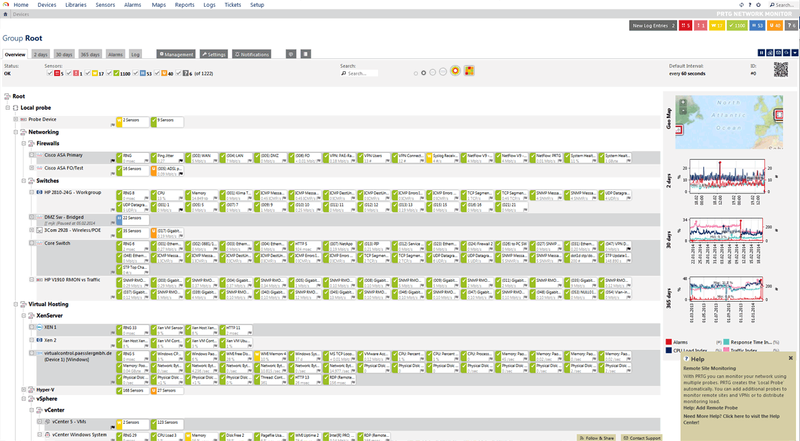
Interface Monitoring Tool example: PRTG
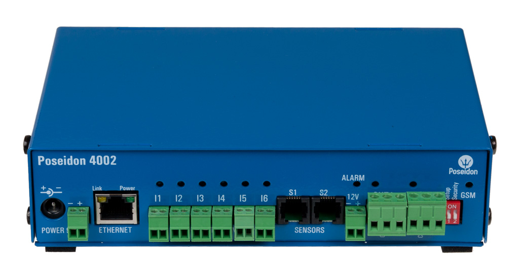
Rack mount environment monitor

Port scanner
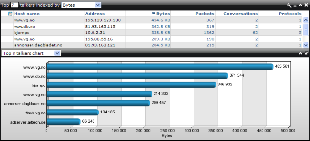
Top Talkers example
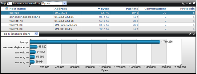
Top Listeners example
Simple Network Management Protocol (SNMP)
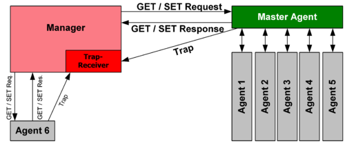
SNMP communication principles diagram
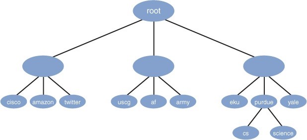
Management Information Base (MIB) structure: top-down hierarchical tree
|
• Packet/network analyzer: is a computer program or piece of computer hardware that can intercept and log traffic that passes over a digital network or part of a network. Used for sniffing network traffic and passively determining which Internet sites your network’s users are connecting to. A network analyzer, also known as a packet or protocol analyzer, or a packet sniffer, is a software or hardware management tool that integrates diagnostic and reporting capabilities to provide a comprehensive view of an organization's network. As data flows across a network, an analyzer will intercept it, log it, and analyze the information according to baseline specifications. Basic network analyzers enable a technician to analyze network traffic on a LAN or DSL connection. Network analyzers also have the ability to provide an administrator with an overview of systems and reports from one location on the network. Full-featured network analyzers offer a variety of monitoring, analyzing, and reporting functions. A network analyzer can be used during troubleshooting to locate problems, but it can also be used as a long-term network monitoring solution. Wireshark and Microsoft Network Monitor are software that can analyze networks.
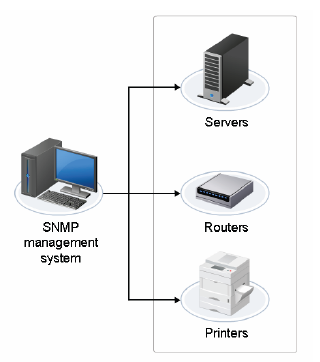
• Interface monitoring tools: Interface monitoring allows you to use classic SNMP-based third-party monitoring tools to continuously query many devices and report their status to a central console in a graphical format. Many network monitoring tools have the ability to send alerts. An alert can be a notification that appears within the tool, or even an email or SMS message that is sent to a preconfigured user. The alert informs the user of an event that occurred. The conditions that triggered the alert are usually configurable so that you can control what you want to be alerted about. After receiving an alert, the user can then investigate the event and take the appropriate action, if any. Often, separate rack monitoring equipment is needed beyond routers and switches for the monitoring of a rack's temperature and humidity. Rack monitoring systems can send alerts, record information, and forward it to a higher- level management system. Some monitoring systems can connect to environmental systems, respond to changing conditions, and automatically perform actions to adjust those conditions, such as activating additional fans. Though interface monitoring may help you detect a threat or alert you to a problem early so that you can address it, the feature does not make any of your network interfaces redundant. Some devices may be fault tolerant, however, which allows the network to withstand a foreseeable component failure and continue to provide an acceptable level of service. This includes protecting the critical components of a network to ensure base-level functioning. Though interface monitoring may be able to detect attacks underway based on metrics like traffic flow, or device statuses, it does not actively prevent intrusions or breaches from occurring. It can, however, alert pertinent individuals to network issues as they occur. A feature built into many switches, routers, or servers, interface monitoring provides statistics about its own interfaces, traffic loads, packet errors, and link statuses, as well as snapshots and historical information. What is another major feature that interface monitoring devices often provide? Alerts. • Port scanner: is an application designed to probe a server or host for open ports. This is often used by administrators to verify security policies of their networks and by attackers to identify services running on a host and exploit vulnerabilities. A port scanner is used to quickly collect service information on all computers on a network. The port scanner connects to all listening TCP/IP ports to test for a response from services. A port scanner is a type of software that searches a network host or a range of IP addresses for open TCP and UDP ports. A port scanner looks for open ports on the target system and gathers information including whether the port is open or closed, what services are running on that port, and any available information about the operating system. Administrators can use a port scanner to determine what services are running on the network and potential areas that are vulnerable. Example: Nmap. A port scanning attack occurs when an attacker scans your systems to see which ports are listening in an attempt to find a way to gain unauthorized access. If you suspect that a user is running a rogue service on your network, which tool would you use to find it? A port scanner. • Top talkers/listeners: Top talkers are the computers sending the most data, either from your network or into your network. Top listeners are the hosts receiving the most data, i.e. streaming or downloading large amounts of data from the internet. Network traffic analysis involves identifying top talkers and top listeners on the network. • SNMP management software: Simple Network Management Protocol (SNMP) is an Application-layer (Layer 7) protocol used to collect information from network devices for diagnostic and maintenance purposes. SNMP includes two components: management systems and agent software, which are installed on network devices such as servers, routers, and printers. The agents send information to an SNMP manager. The SNMP manager can then notify an administrator of problems, run a corrective program or script, store the information for later review, or query the agent about a specific network device. An SNMP-managed network consists of three key components: network-connected devices, SNMP agents, and a management station. The SNMP is an Internet protocol that enables administrators to monitor and manage network devices and traffic. SNMP uses ports 161 and 162 to collect information from and send configuration commands to networking devices such as routers, switches, servers, workstations, printers, and any other SNMP-enabled devices. SNMP requires that the management agent feature to be installed or enabled on each network element to be monitored. SNMPv1 is an unsecure protocol because its authentication is passed in cleartext. Initial security features were added to the protocol in 1993 with the introduction of SNMPv2. SNMPv3 added cryptographic security to secure data and user credentials. - Trap: Asynchronous notification from agent to manager. SNMP traps enable an agent to notify the management station of significant events by way of an unsolicited SNMP message. Includes current sysUpTime value, an OID identifying the type of trap and optional variable bindings. Destination addressing for traps is determined in an application-specific manner typically through trap configuration variables in the MIB. The format of the trap message was changed in SNMPv2 and the PDU was renamed SNMPv2-Trap. While in classic communication the client always actively requests information from the server, SNMP allows the additional use of so-called "traps". These are data packages that are sent from the SNMP server to the client without being explicitly requested. - Get: GetRequest is a manager-to-agent request to retrieve the value of a variable or list of variables. Desired variables are specified in variable bindings (values are not used). Retrieval of the specified variable values is to be done as an atomic operation by the agent. A Response with current values is returned. - Walk: The snmpwalk command line utility displays a list of all results that lie within the subtree rooted on the specified object ID (OID). Snmpwalk can also be used to display a single object if an exact instance of an OID is specified. - MIBS: Management Information Base is a formal description of a set of network objects that can be managed using the Simple Network Management Protocol (SNMP). A MIB is a database used for managing the entities in a communication network. Most often associated with the Simple Network Management Protocol (SNMP), the term is also used more generically in contexts such as in OSI/ISO Network management model. A management information base (MIB) is a hierarchical virtual database of network (or other entity) objects describing a device being monitored by a network. It's structure is best understood as a top-down hierarchical tree. |
• Alerts: Interface monitoring allows you to use classic SNMP-based third-party monitoring tools to continuously query many devices and report their status to a central console in a graphical format. Many network monitoring tools have the ability to send alerts. An alert can be a notification that appears within the tool, or even an email or SMS message that is sent to a preconfigured user. The alert informs the user of an event that occurred. The conditions that triggered the alert are usually configurable so that you can control what you want to be alerted about. After receiving an alert, the user can then investigate the event and take the appropriate action, if any.
- Email: notification to a preconfigured user (usually an Administrator) via email that an event has occurred.
- SMS: notification to a preconfigured user (usually an Administrator) via text message that an event has occurred.
• Packet flow monitoring: There are two main technologies that you can choose from if you want to perform traffic analysis on your network; flow analysis and packet analysis. A flow is a traffic stream with a common set of identifiers. Typically, a flow is defined by traffic that has the same source IP, destination IP, protocol, source port, and destination port. If any of these variables change, then a new flow is defined. A network analyzer can be used for packet flow monitoring and display both at time of capture and at the time of display. NetFlow, sFlow, IPFIX are all ways to collect information about traffic that is traversing a network. Devices such as routers or switches along the traffic path can generate flow data, based on the traffic that is traversing them. The flow data is sent to a flow collector, which then creates reports and statistics from the flow updates. This process is called flow analysis.
• SYSLOG: Syslog is a simple, easy to set up logfile-based monitoring system that collects data from many types of devices via the syslog agent that is already present on most operating systems and networked devices. Syslog is not a native Windows application, even in Windows Server 2012. You’ll have to download and install the third party syslog agent for Windows operating systems. Syslog is a term used to define the process of logging program messages or data logs. The term collectively includes the software or operating system that generates, reads, and analyzes log files. A log file is a record of actions and events performed on an operating system. There are three common types of log files: system, general, and history files.
• SIEM: Security Information and Event Management (SIEM) includes different network monitoring tools. The following are a few tools included:
• Environmental monitoring tools: Environment monitors are hardware tools that ensure that environmental conditions do not spike or plummet to place temperatures above or below equipment specifications. In addition to temperature, environment monitors allow you to monitor the humidity in the environment where the network devices are placed. By monitoring humidity, you can ensure that condensation does not build in devices, and that there is enough humidity to decrease static electricity buildup. You can monitor a computer room with a humidity monitor or you can use sensors to monitor the temperature inside servers, workstations, and components such as hard drives. Often, separate rack monitoring equipment is needed beyond routers and switches for the monitoring of a rack's temperature and humidity. Rack monitoring systems can send alerts, record information, and forward it to a higher-level management system. Some monitoring systems can connect to environmental systems, respond to changing conditions, and automatically perform actions to adjust those conditions, such as activating additional fans.
- Temperature
- Humidity
• Power monitoring tools: provide information about power quality, demand, and flow (in a data center).
• Wireless survey tools: is the process of planning and designing a wireless network that provides a wireless solution that will deliver the required wireless coverage, data rates, network capacity, roaming capability, and QoS. The survey will require a site visit to identify installation locations for access points and to test for radio frequency (RF) interference. Wireless survey tools will be required to perform parts of the site survey. Most surveys can be performed using software, a WAP, and either a client with a Wi-Fi adapter or a field-strength measuring device. Youre place the WAP and then move the client/field-strength measuring device test the signal strength of connections within the range that WAP will service, preferably testing from actual client desk locations. You can perform site surveys by using tools such as NetStumbler or AirSnort. These will also allow you to see if any rogue access points have been installed on the network. An RF spectrum surveys require specialized RF equipment. There are various types of spectrum analyzers ranging from large and expensive bench-top units to portable and PC-based analyzers.
- Email: notification to a preconfigured user (usually an Administrator) via email that an event has occurred.
- SMS: notification to a preconfigured user (usually an Administrator) via text message that an event has occurred.
• Packet flow monitoring: There are two main technologies that you can choose from if you want to perform traffic analysis on your network; flow analysis and packet analysis. A flow is a traffic stream with a common set of identifiers. Typically, a flow is defined by traffic that has the same source IP, destination IP, protocol, source port, and destination port. If any of these variables change, then a new flow is defined. A network analyzer can be used for packet flow monitoring and display both at time of capture and at the time of display. NetFlow, sFlow, IPFIX are all ways to collect information about traffic that is traversing a network. Devices such as routers or switches along the traffic path can generate flow data, based on the traffic that is traversing them. The flow data is sent to a flow collector, which then creates reports and statistics from the flow updates. This process is called flow analysis.
• SYSLOG: Syslog is a simple, easy to set up logfile-based monitoring system that collects data from many types of devices via the syslog agent that is already present on most operating systems and networked devices. Syslog is not a native Windows application, even in Windows Server 2012. You’ll have to download and install the third party syslog agent for Windows operating systems. Syslog is a term used to define the process of logging program messages or data logs. The term collectively includes the software or operating system that generates, reads, and analyzes log files. A log file is a record of actions and events performed on an operating system. There are three common types of log files: system, general, and history files.
- System: System logs are often predetermined by the operating system itself and are a record of events logged by the operating system.
- General: General logs are a type of system log that contains information about device changes, installation/uninstallation of device drivers, and any other system changes.
- History: History logs record information, such as the type of log, the time of event occurrence, the name of the user who was logged on at the time of the event (or who caused the event), keywords, any identification numbers, and what category (or categories) the event belongs to. The format may differ based on the operating system used.
• SIEM: Security Information and Event Management (SIEM) includes different network monitoring tools. The following are a few tools included:
- McAfee Enterprise Security Manager®
- CNAM Threat Defense Platform NETMONASTERY®
- EiQ Networks SecureVue®
- HP ArcSight®
- IBM Security QRadar SIEM®
- NetIQ Sentinel®
• Environmental monitoring tools: Environment monitors are hardware tools that ensure that environmental conditions do not spike or plummet to place temperatures above or below equipment specifications. In addition to temperature, environment monitors allow you to monitor the humidity in the environment where the network devices are placed. By monitoring humidity, you can ensure that condensation does not build in devices, and that there is enough humidity to decrease static electricity buildup. You can monitor a computer room with a humidity monitor or you can use sensors to monitor the temperature inside servers, workstations, and components such as hard drives. Often, separate rack monitoring equipment is needed beyond routers and switches for the monitoring of a rack's temperature and humidity. Rack monitoring systems can send alerts, record information, and forward it to a higher-level management system. Some monitoring systems can connect to environmental systems, respond to changing conditions, and automatically perform actions to adjust those conditions, such as activating additional fans.
- Temperature
- Humidity
• Power monitoring tools: provide information about power quality, demand, and flow (in a data center).
• Wireless survey tools: is the process of planning and designing a wireless network that provides a wireless solution that will deliver the required wireless coverage, data rates, network capacity, roaming capability, and QoS. The survey will require a site visit to identify installation locations for access points and to test for radio frequency (RF) interference. Wireless survey tools will be required to perform parts of the site survey. Most surveys can be performed using software, a WAP, and either a client with a Wi-Fi adapter or a field-strength measuring device. Youre place the WAP and then move the client/field-strength measuring device test the signal strength of connections within the range that WAP will service, preferably testing from actual client desk locations. You can perform site surveys by using tools such as NetStumbler or AirSnort. These will also allow you to see if any rogue access points have been installed on the network. An RF spectrum surveys require specialized RF equipment. There are various types of spectrum analyzers ranging from large and expensive bench-top units to portable and PC-based analyzers.
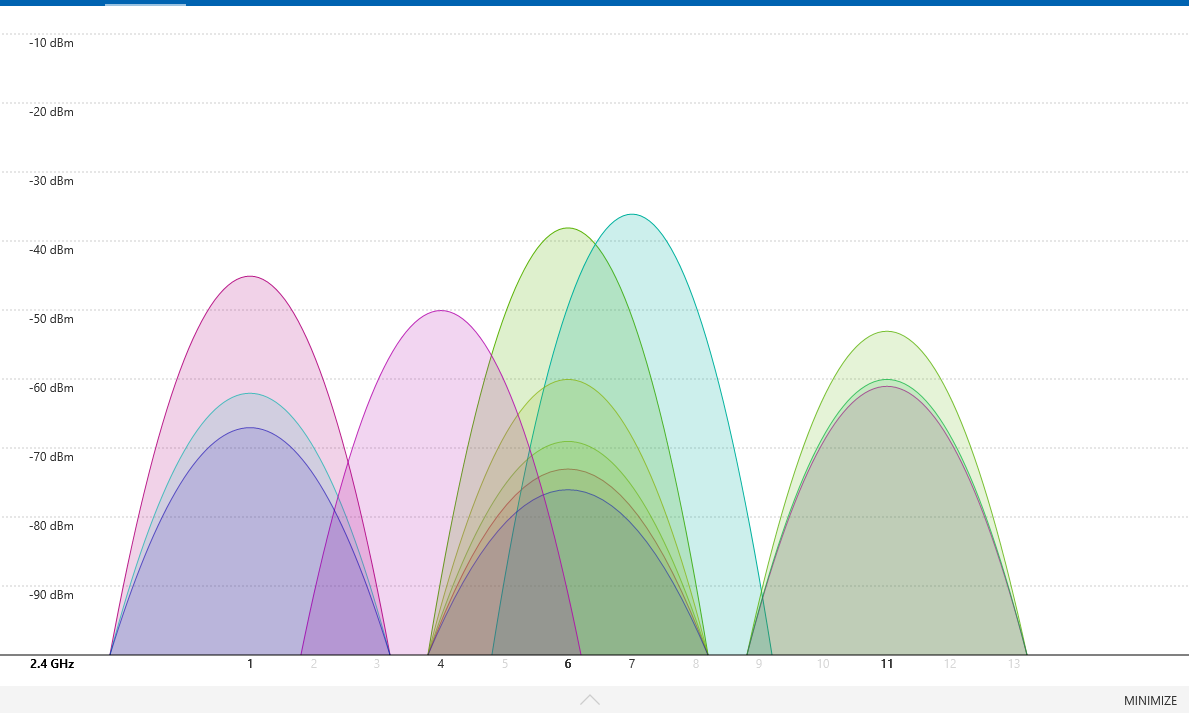
Wireless (wi-fi) analyzer: This view shows the wifi channels used and how strong the signals are – the higher the peak the stronger the signal.
|
• Wireless analyzers: A wireless analyzer is piece of software or hardware that is used to analyze the physical aspects of wireless networks. This includes items such as: spectrum analysis, finding WAPs, reporting service set identifiers (SSIDs), channel usage, signal strength, and identifying noise sources.
|
Network Diagnostics
There are various tools available to perform network diagnostic tests to determine concern areas and issues. The tools provide real-time issues and methods to troubleshoot most common issues. Some of the activities performed by network diagnostics tools are:
There are various tools available to perform network diagnostic tests to determine concern areas and issues. The tools provide real-time issues and methods to troubleshoot most common issues. Some of the activities performed by network diagnostics tools are:
- Monitor end-to-end application response time
- Analyze network traffic
- Manage device performance
- Monitor and alert availability, bandwidth utilization, and health of devices
- Provide network diagnostics for troubleshooting and resolving issues
- Offer network discovery tools that facilitate IP address management, port mapping, and ping sweeps.
- Port mapping translates addresses of packets to a new address. The translated packets are then routed based on the routing table.
- Ping sweeps establish a range of IP addresses to locate active hosts within a given range. Ping sweep can be performed by using tools such as fping and map.
- Provide tools for real-time NetFlow analysis, configuration, and device management
2.2 Given a scenario, analyze metrics and reports from
monitoring and tracking performance tools
One of the first tasks in setting up network monitoring is to establish a baseline. How do you establish a baseline? What is the purpose of performing a network baseline? Which document provides a visual representation of network-related data, such as performance monitor reports, and should be included in your network documentation? You suspect that some of your users are using a lot of network bandwidth by running programs such as BitTorrent. How can you minimize their effect on your network’s valuable data transmissions? What feature is typically built into a switch, router, or server and allows a device to provide statistics on its own interface, including transmit and receive traffic loads, packet errors, and link status? |
• Baseline: is a record of a system's performance statistics under normal operating conditions. A network baseline documents the network's current performance level and provides a quantitative basis for identifying abnormal or unacceptable performance. It can also reveal where bottlenecks are impeding system performance, and provide evidence for upgrading systems to improve performance. The longer the monitoring period, the better, but the duration should be 24 hours per day for the desired monitoring period. The baseline establishes what normal traffic is for a network to make attack and latency troubleshooting easier.
- For example, if a company is expanding a remote office that is connected to the corporate office with a fractional T1, the baseline can help determine if there is enough reserve bandwidth to handle the extra user load, or if the fractional T1 needs to be upgraded to a full T1. - The Network Baselining Process: Creating and applying a baseline is a cyclical process. The number, type, and frequency of tests performed and recorded in the baseline will vary depending upon the systems and the needs of the organization. The organization must also decide how often to establish a new baseline to reflect current performance. Typically, you will record baseline measurements to a log file that you can review later, rather than examining the measurements in real time. Most performance or network monitoring systems enable you to save log data. For example, in Windows Server 2012 R2, Performance Monitor® gives you the option to record data directly to log format. When you log data in Performance, you can select all counters for a selected object, or specific counters. You can examine the counter values by selecting the counters to add when you open the log file in Chart view. • Bottleneck: a component of a system that performs poorly when compared to other components and reduces the overall system performance. • Log management: comprises an approach to dealing with large volumes of computer-generated log messages (also known as audit records, audit trails, event-logs, etc.). Log Management generally covers:
• Graphing: Provide visual representation of network-related data, such as the graph from a network performance monitor. • Utilization: Provide usage logs and reports to measure network utilization and performance. Utilization logs can be used to share information about network-related data such as usage and efficiency, but logs are often presented in an unintuitive format for laypersons. - Bandwidth: The average number of bits of data that can be transmitted from a source to a destination over the network in one second. Identifying the different types of traffic on your network and shaping the network through the use of traffic profiles is the most effective method of limiting bandwidth for non-business or low-priority traffic. - Storage: is a quantitative measure, expressed as a percentage, of how well the available data storage space in an enterprise is used. - Network device CPU: Monitoring Central Processing Unit (CPU) usage is important in order to stay on top of your network's performance. If you continuously monitor CPU usage on all your network devices, you will be able to spot network device overloads before they lead to poor network performance or even downtimes. This way, a Windows CPU monitor helps you to guarantee that your network devices are always available, allows you to distribute loads evenly, and shows you when you should buy additional resources. - Network device memory: Monitoring memory usage helps you to detect network overloads at an early stage, before they result in downtimes or data loss. It also helps you to identify underused servers, and redistribute loads accordingly. Using a memory usage monitor is also very important for virtualized environments. - Wireless channel utilization: If an AP is assigned to a channel, how busy does that channel look from its perspective? Not data the AP may itself be passing over the channel, but the level of traffic it perceives, including "chatter" from other APs and clients on the same channel. Understanding how busy the channel is by considering all sources tells us how often the AP has an opportunity to use the channel. It may also give us a indication of how much co-channel contention (CCI/CCC) our AP may be exposed to. Once we know how busy a channel is, we can decide whether using this channel is viable for our AP. Channel Utilization indicates how much 802.11 traffic the AP can "hear" on its channel, from all sources. The statistic is a percentage figure. This will include all 802.11 frames that the AP can hear from all APs and clients in the vicinity. It indicates the amount of time that the AP considers the channel to be busy. For best performance of latency-sensitive applications over wireless, such as voice, plan to keep RF channel utilization under 50%. This is not a hard-and-fast rule, but a best practice for most networks supporting data and voice. |
 Link status lights
• Link status: You should regularly monitor link status to make sure that connections and up and functioning. Breaks should be found and identified as quickly as possible in order to repair them or find workarounds. A number of link status monitors exist for the purpose of monitoring connectivity and many can reroute (per a configured script file) when a down condition occurs. Link status refers to the health of the link that an interface, such as a router interface, is connected to. Monitoring tools such as SNMP are used to track link status and generate an alert if the link status is down. You'll see two different lights on a typical NIC, one green and one amber. Depending on whether the host has network connectivity or not, the lights will be solid, flashing, or out. Sometimes flashing is good, sometimes it's not! Here's a guide to the colors you'll see on a NIC:
- A solid green light indicates connectivity is present. This link light is generally either green or off. Green is good, off is not! That light should stay a solid green.
- A flashing green light is a sign of intermittent connectivity, which is a fancy way of saying "one minute the PC is on the network, the next minute it's not". Most likely, either the NIC or the cable connected to the NIC is going bad. With the green light, flashing is not desirable.
- If a port has a solid orange light, this means the software inside the switch shut down the port, either by way of the user interface or by internal processes. The ports may have been disabled inside the switch by an operator.
- Flashing orange lights indicate collisions. You'll see this flash occasionally even on a healthy network, but you don't want to see it flash so often that it looks like a solid amber light!
 Logic Monitor: Interface Monitoring Tool
• Interface monitoring: is typically a feature built into a switch, router, or server. The device can provide statistics about its own interfaces. Usually these are transmit (TX) and receive (RX) traffic loads, packet errors, and link status. In most cases, you can get a point-in-time snapshot, as well as some history. You can use classic SNMP-based third-party monitoring tools to continuously query many devices and report their status to a central console in a graphical format. You can typically also set alerts and track trends on interfaces/devices of interest. Logic Monitor is a good tool (www.logicmonitor.com). The following details can be monitored and reported based on the type of interface being examined:
- Errors: can be checked by inspecting the devices' log. Each transaction is recorded in a log so that we can identify the amount and type of traffic, as well as any system errors or dropped packets to determine if further network changes or device configuration is needed.
- Utilization: by checking the logs for common activities, or data packet types, we can determine the propensity of each type of packet. By doing this, we can figure out the more popular activities on the network. With this information we can tailor our network to suit.
- Discards: if packets are being dropped, we need to know the cause of this:
- Interface resets: logs can actively report when a NIC, switch or router was reset, either through power failure, manual reset or hardware fault. From this we can determine the reliability of the network at this point and make decisions on replacing components which appear to be more sensitive to reset, or inactivity. If an area of the network is being attacked by an outside influence (e.g. DoS attack, or Smurf attack) one specific node is targeted (e.g. Router) until it is unable to function. Often at this point safety protocols will cause the device to reset, clearing the problem but causing inactivity for the amount of time the device is rebooting and initializing.
- Speed and duplex:
--> The speed of the port can be set within the router itself (Baud rate). Higher speeds however are only achievable if both devices at both ends of teh cable are capable of transmitting at the higher speed. Higher speeds also run the risk of an increased number of dropped packets, leading to some congestion, or latency issues.
--> The duplexing mode of the port can be set either to simplex (one way only, such as with an uplink, or a fibre connection on a FDDI ring as this is designed to go in one direction only) and therefore allowing use of the full bandwidth, half-duplex (where half of the bandwidth is used for transmissions in one direction as the other half is used for the other direction) or full duplex (where both directions are possible, full bandwidth, but not at the same time).
- Errors: can be checked by inspecting the devices' log. Each transaction is recorded in a log so that we can identify the amount and type of traffic, as well as any system errors or dropped packets to determine if further network changes or device configuration is needed.
- Utilization: by checking the logs for common activities, or data packet types, we can determine the propensity of each type of packet. By doing this, we can figure out the more popular activities on the network. With this information we can tailor our network to suit.
- Discards: if packets are being dropped, we need to know the cause of this:
- Could it be that packets cannot be handled due to congestion, so the packet reaches its TTL?
- Is the packet important?
- By dropping the packet will this have cumulative effects for teh network (e.g. missing heartbeat signals may affect the performance and synchronization between servers).
- Did we set a rule to deliberately drop the packet if it is encountered on the network? In which case where are they being generated? If we can determine the source we can block the creation of these packets by disabling the appropriate service on the host PC.
- Do we have a routing loop on the network causing congestion? Should we implement Spanning Tree Protocol (STP) or an equivalent routing protocol to counter routing problems?
- Interface resets: logs can actively report when a NIC, switch or router was reset, either through power failure, manual reset or hardware fault. From this we can determine the reliability of the network at this point and make decisions on replacing components which appear to be more sensitive to reset, or inactivity. If an area of the network is being attacked by an outside influence (e.g. DoS attack, or Smurf attack) one specific node is targeted (e.g. Router) until it is unable to function. Often at this point safety protocols will cause the device to reset, clearing the problem but causing inactivity for the amount of time the device is rebooting and initializing.
- Speed and duplex:
--> The speed of the port can be set within the router itself (Baud rate). Higher speeds however are only achievable if both devices at both ends of teh cable are capable of transmitting at the higher speed. Higher speeds also run the risk of an increased number of dropped packets, leading to some congestion, or latency issues.
--> The duplexing mode of the port can be set either to simplex (one way only, such as with an uplink, or a fibre connection on a FDDI ring as this is designed to go in one direction only) and therefore allowing use of the full bandwidth, half-duplex (where half of the bandwidth is used for transmissions in one direction as the other half is used for the other direction) or full duplex (where both directions are possible, full bandwidth, but not at the same time).
2.3 Given a scenario, use appropriate resources to
support configuration management
• Archives/backups: it is commonplace to use NAS storage to back up key corporate data such as user accounts and common shared folders. More recently, files are being stored on a SharePoint intranet space. You should always keep documentation, such as archives and backups, as up to date as possible. Any replacement or upgrade of network equipment could well require an update to a physical network diagram. Any change in the config on a router or switch will require a change in the logical network diagram and the backup. To track these chagnes and their documentation, many companies use job logs that list the change that was made, when it was made, and when it was documented. This archived and backed up information can be used to troubleshoot and sometimes even restore parts of a network when needed.
• Baselines: are an important part of network documentation. If you don't know what your resources look like when they are healthy, then how will you know what they look like when they are sick? There are many software programs, such as SolarWinds and ManageEngine, that can assist you in tracking your normal resources and pointing out anomalies.
• On-boarding and off-boarding of mobile devices: Many organizations have moved to a bring-your-own-device (BYOD) strategy that allows employees to use their own devices on the company networks. This saves the company money but presents a new challenge for IT. Depending on the type of device and the access required (email, intranet, etc.), the administrator must configure the network (and often the device itself) so that two will work together. This process is referred to as on-boarding the user's device, much like a new employee is on-boarded by the HR department. At the end of the life cycle of the device (or the employee) the device must be made to no longer have the privilege to communicate on the organization's network. This is referred to as off-boarding the device.
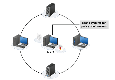
NAC governs access on device network interconnections.
|
• NAC: Network access control (NAC) is a general term for the collected protocols, policies, and hardware that govern access on network interconnections. NAC provides an additional security layer that scans devices for conformance and allows or quarantines updates to meet policy standards. Security professionals will deploy a NAC policy according to an organization's needs based on three main elements: the authentication method, endpoint vulnerability assessment, and network security enforcement. Once the NAC policy is determined, professionals must determine where NAC will be deployed within their network structure.
|
• Documentation: the main reason for keeping detailed network documentation is that in case of a disaster, it will help you rebuild quickly. Although each network is unique, there are common documents that each network administrator should have at hand.
- Network diagrams (logical/physical): Provide the location and routing information for network devices. They are also known as network maps.
--> Logical: Logical network diagrams contain routing topology and node trust relationships. Additionally, they contain node IP addresses, device FQDNs, and application types. This document details the connectivity between subnets, listing IP address ranges and teh location of network devices, switches and routers. It focuses on the flow of traffic across the organization and often does not take into account the physical layout of the building(s) that comprise the network. Due to its logical nature, groupings may be by project, department, or site.
--> Physical: describes the physical structure of the network and how devices are arranged and connected to each other physically.
This is a 'blueprint' or 'floor plan' detailing the exact layout of the building showing where specific cables and components are laid. Metrics here are the port number of the socket, its respective port in the patch panel, which port the panel port connects to in the switch, the distances of cables, the type (and therefore speed) of cables to be used. This is used by an engineer to ensure that the layout of the actual cables is accurate.
- Asset management: is the process of listing (on a database) and tagging devices owned by the company for the purposes of audit tracking.
- IP address utilization: As your network grows and changes and devices are added and removed, IP address utilization should be monitored and documented for trending purposes, historical analysis, and proactive management.
- Vendor documentation: List the vendors used to service any aspects of your network, including ISPs, computer/device retailers, equipment/computer technicians, and so on. This list should include their contact information, services they provide, rate, and any additional comments about their service or performance.
- Internal operating procedures/policies/standards: Provide guidelines and the appropriate method for performing network management tasks. Documented procedures can include: hardware selection, new user creation, security policies and procedures, and troubleshooting tips.
2.4 Explain the importance of implementing network segmentation
• SCADA systems/industrial control systems: Supervisory control and data acquisition (SCADA) is a computer system for gathering and analyzing real time data. SCADA systems are used to monitor and control a plant or equipment in industries such as telecommunications, water and waste control, energy, oil and gas refining and transportation. A SCADA system gathers information, such as where a leak on a pipeline has occurred, transfers the information back to a central site, alerting the home station that the leak has occurred, carrying out necessary analysis and control, such as determining if the leak is critical, and displaying the information in a logical and organized fashion. SCADA systems can be relatively simple, such as one that monitors environmental conditions of a small office building, or incredibly complex, such as a system that monitors all the activity in a nuclear power plant or the activity of a municipal water system. For companies that employ SCADA systems to gather data remotely into a central computer, network administrators have begun to isolate these networks. Network administrators are separating SCADA systems into their own network segments known as security zones, where, among an array of hardware and software security, firewalls are implemented. In other words, two components of these isolated networks are a network segment and a firewall. We have to make sure that these SCADA connected systems are completely secure and that no one can access these very large and very important industrial systems from outside of the organization.
• Legacy systems: Legacy systems are a security risk because they are end of life and out of vendor support, which means that the vendor no longer supplies patches for critical security bugs. Often, network administrators will create a network segment for so-called legacy systems since they often can’t be patched because they’re no longer supported by the vendor.
• Separate private/public networks: Network administrators often separate public and private networks on corporate LANs because public networks have direct access to the Internet. Public networks are exposed, at least in part, to the Internet. This exposure makes them more vulnerable to attacks. Sometimes, these public networks are referred to as DMZs to designate their lack of protection outside the corporate firewall.
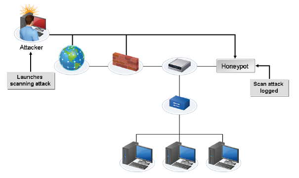
A honeypot scanning for attacks.
You set up a honeypot on the network as part of your overall security plan. Why should it be placed into a network segment? |
• Honeypot/honeynet:
--> A honeypot is a system that’s typically set up on a network to help catch intruders and hackers as a low-hanging fruit target. A honeypot is a security tool that lures attackers away from legitimate network resources while tracking their activities. Honeypots appear and act as a legitimate component of the network but are actually secure lockboxes where security professionals can block the intrusion and begin logging activities for use in court or even launch a counterattack. The act of luring individuals in could potentially be perceived as entrapment or violate the code of ethics of your organization. These legal and ethical issues should be discussed with your organization's legal counsel and human resources department. Honeypots can be software emulation programs, hardware decoys, or an entire dummy network, known as a honeynet. A honeypot implementation often includes some kind of IDS to facilitate monitoring and tracking of intruders. Some dedicated honeypot software packages can be specialized types of IDSs. --> Two or more honeypots on the same network form a honeynet. This is used when an organization is very large and a single honeypot server won't do the job. The honeynet simulates a production network but is actually heavily monitored and isolated from the true production network. It can be used to draw the attacker deeper in and give them that much more opportunity to make a mistake that will get them caught. |
• Testing lab: a testing lab's lack of security control makes it necessary to isolate it with a network segment. Most testing labs are far outside the control of security, so segmentation is necessary to ensure the safety of the rest of the network.
• Load balancing: The key function of a load balancing device is to divide the amount of work shared among the devices on a network. Distributing work evenly across servers for processing efficiency is the goal of load balancing. If an administrator wanted to share processing load between servers, he or she should look for hardware or software that provides load balancing.
--> Network load balancing with segmentation balances the load by separating traffic from other segments. Only traffic destined for a particular segment will reach that segment and only affects that segment. How is network segmentation used in network load balancing? Because incoming and outgoing traffic are limited to systems inside the segment.
• Performance optimization: is the process of comparing current performance with the baseline and finding ways to achieve optimal performance after maintenance and upgrades have taken place. It can involve factors such as:
- Stopping and disabling unnecessary services on the PC
- Offloading services onto other servers to free up processing capability, or RAM
- The use of a RAID system to reduce latency through striping (e.g. RAID 6)
- The use of a iSCSI fibre to transfer files at the data block level rather than having to resolve them into the OS for conversion as part of the transfer
- The addition of more, or faster RAM to increase system scope
- The use of NUMA (non uniform memory access) to share hardware capacity across several virtual PCs
- The updating of virtual hard drives from VHD to VHDX in order to break the 2 Tb limit to much larger drive sizes
|
• Security: We network computers to share resources, and then we have to address a myriad of security issues and threats. We address these network security issues and threats using both hardware and software. Also, many protocols have evolved over the past 20 years or so that are specifically designed to mitigate network security threats. Keeping resources secure often means segmenting them first; then you can decide who is allowed to get to what resource.
|
• Compliance: To be in compliance means to meet an established standard. That standard might be enforced by the government or it might be enforced by your organization. In either case, it's unlikely that the exact same standard will apply in the exact same way to all parts of your network or your users. For this reason, network segmentation can be used so that, when you desire, the standard can be different for different parts of your organization. This gives you more flexibility to apply a higher standard to areas that warrant it and a lower standard to areas that don't.
2.5 Given a scenario, install and apply patches and updates
• OS updates: Operating System (OS) updates should be performed on a regular basis on your servers and client systems. This is because most software is usually not fully tested and debugged when it’s released because that would take far too long. Instead, the software is released when it seems ready and is partially tested, and then the customers will discover the bugs as the software is used. When this happens, the software company will respond with a fix. Depending on the severity of the bug, the fix may come as a patch or it may just be added to the next big group of patches and other updates. Microsoft, for example, releases a new group of patches for its OSes and other software on the second Tuesday of each month, which is affectionately referred to as Patch Tuesday. However, Microsoft and all vendors might release a new patch at any time that it’s deemed important enough to release. In general, you should have a system that allows you to verify that the patch is in fact a good thing on a test system and then, once it’s verified, enforces that it’s installed on all the of the appropriate systems. There is a myriad of software to help you with this function.
• Firmware updates: Firmware is neither software nor hardware but somewhere in the middle. The BIOS on a PC is an example of firmware. Another example would be the bootstrap that supports your routers and switches. It’s not always necessary to update firmware when you update software. Typically, you will update firmware on a router, switch, or even PC by simply replacing the hardware and obtaining the new firmware with the new hardware. That said, it is possible to update firmware when necessary to run a specific service or application. For example, an old PC might require a BIOS update to support USB or an advanced video card. Finally, you should take care to supply reliable power when updating any type of firmware, because a loss of power during the update could render the device rather useless until you fix it with another more complicated series of steps, such as using XMODEM or looking for a light on a card. Trust me, you don’t want to get into that, so just make sure that you are on outlet power (not a battery) and that the device stays powered on.
• Driver updates: Drivers are software that allows the hardware to communicate with the operating system. They are generally very specific to a type of hardware and a type of operating system. That means if you change the hardware or the operating system, you will have to change the driver as well. Drivers can generally be updated by installing the new driver to take the place of the old driver. Some of the latest operating systems even offer a driver rollback option just in case the new driver isn’t what you expected. Of course, you should also perform a backup including the system state before changing any important drivers.
• Feature changes/updates: Don’t make changes just because you can; instead, make only the change that you have to in order to support a new feature that you really need. Making changes because they are available, even though you don’t really need the new feature, can lead to headaches down the road when something else goes wrong and you realize that the change you made caused that to happen. If you really did require the new feature, then you probably won’t be kicking yourself when the other problem arises; otherwise, you probably will.
• Major vs. minor updates: A major update is an overall change to the way that the software or hardware is installed and functions. Major updates that could affect security or productivity should be scheduled to be performed whenever the software or hardware vendors require. You should not leave those up to chance or worry about whether they will break something. Minor updates that only tweak a setting or service should be performed only when that service or tweak is actually needed or beneficial.
• Vulnerability patches: The biggest problem with a vulnerability patch is that it’s generally public. In other words, at the moment that you are told that you have a potential vulnerability to attack, so are all of the potential attackers! Many organizations have a rule that all critical patches must be installed in the same week that they are released. Some even have a tighter schedule than a week. You should install the patch on a test system and verify that it has prevented the potential threat the attackers have now been informed of in detail.
• Upgrading vs. downgrading: Operating system updates are not always a necessity if you have all of the features that you need and the new system doesn’t give you something new that is of value to you. If you decide to upgrade your OS on some systems, you should make sure that you are not creating a potential problem regarding their connectivity to other systems. Some items to check might be security features and levels that the older systems might not be able to attain but that the newer system might require. In addition, updates of a 32-bit guest OS to a 64-bit guest OS are not possible. This would require a new installation. In any case, you should back up what is working before performing any updates.
- Configuration backup:
2.6 Given a scenario, configure a switch using proper features
Generally speaking, a switch is a device that segments a network at Layer 2 by first building a MAC address table from teh source addresses of hosts that use it and by then using the MAC address table to make frame-forwarding decisions on frames that follow. If you were in charge of your organization's switches, there would be many details that you should know about configuring a switch including virtual local area networks (VLANs), Spanning Tree Protocol, default gateway, and PoE. In addition, you should know how to apply security to a switch by setting a password for access to the switch.
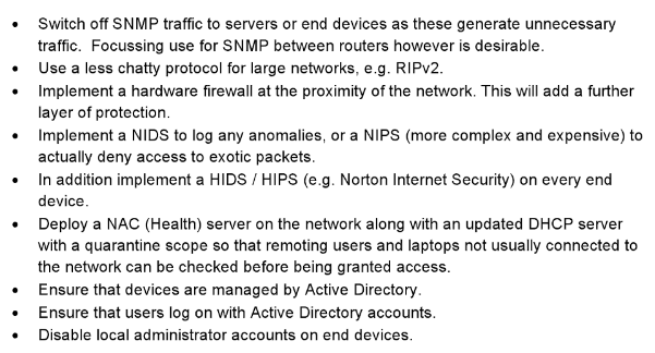
Network configuration without using a VLAN. All systems on the network can see each other. The Students can see the Finance and Administrators computers.
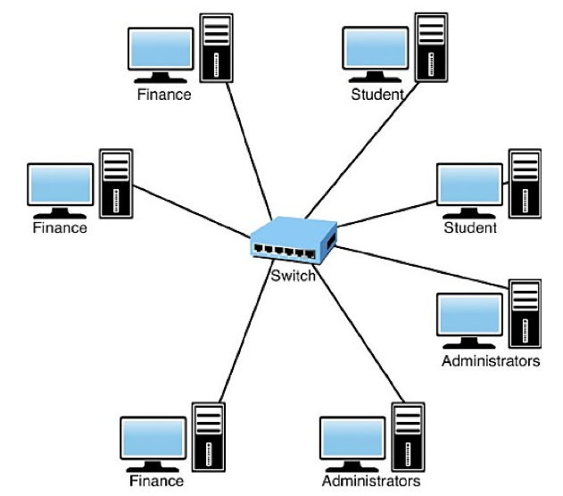
Network configuration using a VLAN
VLAN Segmentation: 
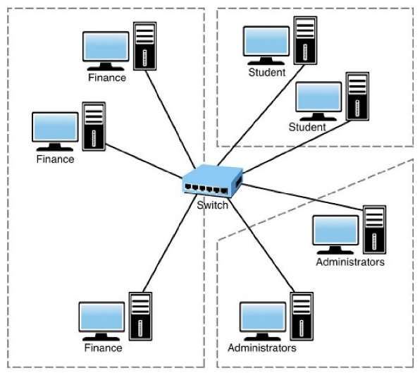
Port based VLAN membership
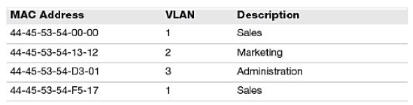
MAC address based VLAN membership
|
• VLAN: Virtual Local Area Network. Both switches and routers have interfaces that are sometimes referred to as physical ports. Depending on the network topology, design, and purpose, these ports can be configured in a variety of ways. These might include the speed of the link, encapsulation type, protocol, duplex, or just whether they are open or shut. On switches, still another configuration is VLAN port assignment. On a Cisco switch, all ports are configured by default to VLAN 1, which is generally configured as the native VLAN as well. The native VLAN is the path that a frame can take with no special tagging from the switches. Even a switch that does not support VLANs can connect to the native VLAN of a switch that does support VLANs (or even a dumb hub). Typically, the native VLAN is used for management traffic, and other VLANs are created to support the departments or functions that you want to segment. The following steps detail how to configure a VLAN on a Cisco router:
Switch1>enable Switch1#configure terminal Switch1(config) #interface vlan 2 Switch1(config-if) #description Finance VLAN Switch1(config-if) #exit Switch1(config) #interface range FastEthernet 0/1 , FastEthernet 0/12 Switch1(config-if-range) #switchport mode access Switch1(config-if-range) #switchport access vlan 2 In this demo we are enabling admin mode. We are then entering configuration mode as admin. We are requesting a VLAN (in this case it is the second VLAN to be built on this switch). Next, we enter a description for the VLAN. Exit is used to exit the configuration interface. Still within the configuration of the VLAN, we configure a range of ports (ports 1 to 12). Within this range we're specifying the access mode, assigning this range of ports to the VLAN. Switch ports can connect to other switches. This cable connection will carry bulk data frames and is referred to as a 'trunk port.' The Ethernet standard 801.q allows the data to be directed to the appropriate VLAN configured on the switch. Switches will share management and tagging information to direct traffic accordingly. - Native VLAN/default VLAN --> A native VLAN: is a VLAN that handles traffic that is not tagged. Any untagged data frames are sent to the VLAN on the switch marked as the 'native VLAN.' The native VLAN is the VLAN designed to handle untagged frames. --> A default VLAN: is the default VLAN on a switch that is used unless another VLAN is created and specified. On a Cisco switch, that default VLAN is VLAN1, which is mandatory, cannot be removed/deleted or renamed. If the VLAN port group exists on only a single device, then those ports would be untagged. The default VLAN automatically has all ports assigned to it and acts as a management structure. If the switch is not connected to any other switch (as far as the VLAN is concerned) the ports themselves are considered 'untagged' as they are not connected to a VLAN group spanning several switches. By default a standalone switch sending frames out to its own ports would be considered to be sending 'untagged' data. - VLAN Trunking Protocol (VTP): is the messaging protocol that switches use to update each other’s VLAN databases. Developed by Cisco, it allows switches to quickly advertise to each other when a VLAN is created or deleted. This saves an administrator some manual labor. If the administrator wishes to extend a VLAN across several switches, he or she would have to manually configure each switch with the same VLANs. With VTP, this is done automatically. VTP is a Cisco-specific communications protocol used by managed switches to propagate VLAN information across the network. VTP info is sent to other switches through trunk ports as advertisements. With VTP configuration changes to VLANs are made to the first switch and then this information is propagated to all of the other switches which will reconfigure themselves with this change. This eliminates the need for the administrator to duplicate the configuration task on every switch. One disadvantage of VTP is that bridging loops can still occur, so the process is not completely automated - the administrator will still have to check and to 'break' (reconfigure) any loops. |
If it weren’t for implementation of the Spanning Tree Protocol (STP) or Rapid Spanning Tree Protocol (RSTP), what would inevitably happen? If a network segment experiences frequent broadcast storms, what can you do to prevent them? You implement STP on bridges and switches in order to prevent loops in the network. Use STP in situations where you want redundant links, but not loops. Redundant links are as important as backups in the case of a failover in a network. A failure of your primary activates the backup links so that users can continue to use the network. Consider this network:
In this network, a redundant link is planned between Switch A and Switch B. However, this setup creates the possibility of a bridging loop. For example, a broadcast or multicast packet that transmits from Station M and is destined for Station N simply continues to circulate between both switches. However, when STP runs on both switches, the network logically looks like this:
|
• Spanning tree (802.1d)/Rapid spanning tree (802.1w): RSTP is the direct successor of STP, and reduces the time to determine network path redundancy from 50 seconds to 20 seconds. Shortest Path Bridging (SPB) is another replacement for STP. It is intended to simplify the creation and configuration of networks, while enabling multipath routing. It is not the direct successor to STP, however.
--> Spanning Tree Protocol (STP) is a Layer 2 protocol used for routing to prevent network switching loops by adopting a dynamic routing method. Whenever there are redundant paths between switches, where either two switches are connected using two different links or a ring of switches connected to each other, a switching loop will occur. STP prevents switching loops and broadcast storms because switches use it to determine if there are any redundant links that may cause a loop. Switches that have STP enabled can be in one of five port states: Blocking, Listening, Learning, Forwarding, or Disabled. The switches use Bridge Protocol Data Units (BPDUs) to exchange data between bridges and calculate route costs. STP is an old protocol. Its full process to determine redundancy actually takes 50 seconds, which is considered too long by modern standards. It has since been replaced by the Rapid Spanning Tree Protocol (RSTP), IEEE 802.1w, which takes only 20 seconds to identify and rectify loops. --> Rapid Spanning Tree Protocol (RSTP) is the direct successor to and replaced STP in 2001, as it only takes 20 seconds to identify and rectify loops (compared to the 50 seconds it takes STP). - Flooding: Because switches, by their nature, flood broadcasts and multicasts out all ports, the first ARP frame sent by a client trying to find a neighbor or a router will cause a Layer 2 broadcast storm. The ARP broadcast will go down one link to the next switch, which will send the broadcast back up the redundant link. This feedback loop will continue indefinitely until there is manual intervention by an administrator. It will cause network utilization to go to near maximum capacity, and the CPU utilization of the switches to jump to 80 percent. This makes the switched segment effectively unusable until the broadcast storm stops. - Forwarding/blocking: During the STP process, all switches in the same broadcast domain elect among them a root bridge (switch), which acts as a reference point for all of the other switches. A switch will then listen for special frames coming from the root to determine if those frames are coming into different ports. If the frames are coming into different ports, then there is a redundant link. The switch will then temporarily block its redundant link, thus eliminating the possibility of a loop. Should the first link fail for some reason, the switch will then unblock the redundant link so that there is connectivity on the network. --> Forwarding: Data is sent and received on a port in this state. Bridge Protocol Data Units (BPDUs) are monitored to determine if the port should return to the blocked state. --> Blocking: User data is not sent or received. Bridge Protocol Data Unit (BPDU) data is received, but the port only goes into another state if other links are unavailable and the spanning tree algorithm determines that the port should change to the forwarding state. - Filtering: Restricts the switch from sending unnecessary Bridge Protocol Data Units (BPDUs) out access ports. |
|
• Interface configuration:
- Trunking/802.1q: Trunk links can be combined to increase bandwidth and reliability in a process called trunking. This is also known as link aggregation, port bonding, port teaming, EtherChannel, and NIC bonding, among other names. The primary purpose of link aggregation is to allow redundant links to combine their bandwidth together without causing spanning tree loops. Link aggregation is typically implemented between switches, although it can be implemented between a node and a switch. Linking two 1 Gbps ports on a server to two 1-Gbps ports on a switch can result in 2 Gbps aggregate throughput. Depending on the implementation, this can result in a redundant connection in case one of the cables or ports fails. However, this still leaves the possibility of the entire switch failing, so some hardware vendors provide proprietary methods for trunking ports across two physically separate switches. Trunking can be used to connect a variety of network hardware, including switch-to-switch, server-to-switch, server-to-server, or switch-to-router. - Tag vs. untag VLANs: VLAN tagging, also known as frame tagging, is a method developed by Cisco to help identify packets traveling through trunk links. Tagging should be used if you are trunking. Because trunking combines VLANs, you need a way to identify which packet belongs to which VLAN and this is easily accomplished by placing a VLAN header (a tag) in the data packet. The only VLAN that is not tagged in a trunk is the native VLAN, and frames are transmitted to it unchanged. - Port bonding (LACP): Although a variety of manufacturer-implemented techniques exist, IEEE 802.1AX-2008 defines a standard for link aggregation. Within the IEEE specification, the Link Aggregation Control Protocol (LACP) provides a method to control the bundling of several physical ports together to form a single logical channel. LACP allows a network device to negotiate an automatic bundling of links by sending LACP packets to the peer. - Port mirroring (local vs. remote): Port mirroring is the practice of duplicating all traffic on one port in a switch to a second port, effectively sending a copy of all the data to the node connected to the second port. Port mirroring is useful as a diagnostic tool when you need to monitor all traffic going to a particular port or node with minimal impact on the network performance. There are a number of reasons why port mirroring can be used (duplicating the data for one port and sending it to another). One of the most common is to monitor the traffic. This can be done locally or remotely: the latter using a remote protocol such as RSPAN (Remote Switched Port Analyzer) instead of SPAN (Switched Port Analyzer). - Speed and duplexing: a switch port setting of "Auto" means the switch port will negotiate with the system’s NIC to determine speed and duplexing settings. Switching offers a dramatic performance improvement over hubs, which simply flood all frames out all ports regardless of which port the intended recipient is plugged into. Most switches allow you to configure the port speed and duplex settings to allow for greater control of the switch performance. The speed and duplex options are similar to those used for NICs, where full duplex allows for a device to send and receive data simultaneously using separate channels for transmitting and receiving and half duplex allows for either sending or receiving data, just not at the same time (think a walkie talkie). - IP address assignment: Switches are typically configured with an IP address for remote management purposes. This should be done on the initial installation of the switch. The precise method of configuration will vary by vendor. - VLAN assignment: When a switch first comes "out of the box", all of the ports are assigned to the native VLAN; usually VLAN 1. The native VLAN does not tag the frames with additional information when they are sent in the network, so the frames on the native VLAN are untagged. When you create additional VLANs, you will then assign the specific ports to the VLANs that you create. Those ports be tagged with the VLAN assignment that you have configured. After you have assigned the VLANs to the ports, then you will connect the appropriate cables to the ports so as to segment the computers and other devices on your network according to your plan. |
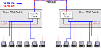
Trunk between two switches carrying traffic from VLAN 100 and VLAN 200 between the Switches
A switch spoofing attack is where an attacking host imitates a trunking switch by speaking the tagging and trunking protocols used in maintaining a VLAN. Traffic for multiple VLANs is then accessible to the attacking host. Port mirroring is useful in what type of scenario? You have installed a new server on your network and plugged it into an available network cable. Everything checks out as working, yet you cannot connect to the rest of the network. What two things do you check first? 
A phone is a good example of full duplex communication. It uses one wire to transmit and one wire to receive data simultaneously.
Walkie talkies are a good example of half duplex communications
|
• Default gateway: In essence, the default gateway is simply the path out of the network for a given device. The default gateway of a switch is the address to which the switch will send any packet that has a destination address that is not in that switch's subnet. You configure the switch with an admin address so that you remotely manage it. That address and its subnet mask establish the switch's local subnet. If the switch receives a packet that is not destined for its subnet, it forwards that packet to the default gateway that you configured. The interface configuration for the default gateway on a Cisco switch is typically a simple command that is configured directly into the interface such as ip default-gateway 192.168.1.254.
• PoE and PoE+ (802.3af, 802.3at): If you have a remote switch or WAP in a place that is not close to a power outlet, it's possible to power some devices from the electric current provided on general Ethernet current. This feature is referred to as Power over Ethernet (PoE). Many switches, IP telephones, embedded computers, WAPs, cameras, and so on can use this feature for convenient installation. The main difference between PoE and PoE+ is an increase in the wattage that can be provided from an Ethernet cable. PoE (802.af) provides 15.4W; whereas PoE+ (802.at) provides 25.5W from the same source.
• Switch management: A switch, such as a common Cisco switch, comes out of the box ready to begin segmenting your network at Layer 2. You don't have to configure it to do that because it's built into the application-specific integrated circuits (ASICs) of the switch.
- User/passwords: What you should configure could include a secure password on every hole through which a person could get administrative access to the switch. This would include the console connections, virtual terminal ports, auxiliary ports, and so on. The precise commands used to configure these passwords vary across vendors and even on products within the same vendor. To protect the switch, safeguards such as required usernames and passwords should be set in place before access is allowed. One method to set up users and passwords is to create user accounts on each switch. In larger environments this becomes tedious and hard to maintain.
- AAA configuration: A more scalable solution (than user accounts on each switch) is to design a centralized user database for administrators on a server built for authentication, authorization and accounting (AAA). Then the switch can check with the AAA server to verify usernames and passwords before allowing admin access to the switch. You can configure most gear for auditing to complete the authentication, authorization, and auditing (AAA) paradigm for that switch.
- Console: setup a secure password on the console connections.
- Virtual terminals: setup a secure password on the virtual terminal ports.
- In-band/out-of-band management:
--> When connecting to the switch for administration of the switch, over the same network as the users, it is referred to as in-band management.
--> If a separate and isolated network was set up for the sole purpose of managing network devices, including the switch, it is an example of out-of-band management. This is an example of isolation that improves security.
• Managed vs. unmanaged:
--> A managed switch can be connected by the administrator locally using the console port, or remotely via a virtual terminal using an IP address. A managed device has a configuration that can be manipulated or changed by an administrator. Most corporate environments use managed switches that can be configured with features such as Port Security, multiple VLANs, and trunking. A managed switch, also called an intelligent switch, is one that includes functions that enable you to monitor and configure its operation. Typically, you connect to the switch by using a web browser or via a dedicated management port. A managed switch provides complete control over how the device functions. It is typically assigned its own IP address and can be managed either directly through the use of a console cable, a Telnet or as a stage connection, or a web browser. Managed switches allow administrators to create logical groupings of ports on a switch, also known as virtual local area networks (VLANs), within a network.
--> An unmanaged switch does not allow local or remote administration, and has no configurable parameters. It is basically taken out of the box, plugged into a power source, and then used as a basic Layer 2 switch to allow connectivity among the devices that are connected to it. An unmanaged switch is significantly less expensive than a managed switch. Unmanaged switches are devices that perform switching without user intervention. In other words, the functions of an unmanaged switch cannot be controlled.
2.7 Install and configure wireless LAN infrastructure and implement the appropriate technologies in support of wireless capable devices
• Small office, home office wireless router: Companies like Cisco and Belkin have made installing a SOHO wireless router a real no-brainer. The devices generally come with an intelligent wizard built into them that asks the installer a few questions and configures the appropriate settings for DHCP, DNS, security, and so on. The cables and connections are generally color coded as well, to make it even easier. You should take into account environmental factors, such as the distance between the client and the wireless router as well as the type of construction that is between them. These can affect the power of the intended signal and therefore make any interference from other signals more pronounced. You should take care as to where you place a wireless router; be sure that there are no other devices in the area that can cause interference and that it is not near any large metal objects. Again, generally speaking, if you follow the instructions, then you'll be fine. A dual-band router is simply one that operates on two different frequencies (such as 2.4 GHz and 5.0 GHz). These are often used in Small Office/Home Office (SOHO) environments.
• Wireless access points: In larger installations, you may use multiple WAPs that overlap each other in regard to their sending/receiving range.
- Device density: When planning the placement of APs, it is important to take density into consideration. Density normally refers to the number of users within an area (a university campus, for example, would be said to have high density), but it can also refer to device density (the number of devices within an area). High density means a high number within a small area, and the single biggest source of interference is often the devices themselves. Ratio of users to APs?
- Roaming: How much overlap you will need will depend on your specific installation, but typically 10-20% overlap at a minimum is desired. This overlap is to provide for roaming for the users so they can continue to use a device as they move through your building/campus or a defined part of it, such as a break area or cafeteria.
- Wireless controllers: The hand-off of signals between WAPs (when users are roaming and need to remain connected to wifi) are generally accomplished using wireless controllers that organize signals among many WAPs.
- VLAN pooling: VLAN pooling is a mechanism whereby wireless access points can choose from among several different available VLANs to assign incoming client connections. This strategy distributes and load balances wireless client traffic among multiple VLANs so that no single network segment is overwhelmed by too many wireless client connections. VLAN pooling is a feature that eneables you to group multiple wireless controller VLANs to form a VLAN pool. You can configure a VLAN pool to load-balance sessions evenly across multiple VLANs. Individual VLANs are then assigned dynamically from the pool, using a round robin algorithm, when a wireless client accesses the network. This can be a very efficient way of load balancing wireless clients on your network.
- LWAPP: LWAPP is the name of the protocol used to control several WAPs at once. As well as sending config info to several WAPs we can also monitor traffic on specific WAPs. LWAPP is implemented on a central server and can manipulate and monitor several WAPs at the same time. LWAPP works on OSI layers 2, 3, and 4.
• Wireless bridge: is a bridge between Access Points (APs). This device is used to extend the physical network by passing wireless frames on to a further access point. The bridge itself does not change the wireless frame but retransmits it onto a neighboring access point. It is used to forward data onto a WAP which is out of range from the host WAP alone (e.g. to reach a neighboring building), thereby extending the wireless network.
• Site surveys: are the process of performing an audit of the relative distances and power strengths for each WAP. The range of each WAP is mapped onto a site floor plan to determine where overlaps occur, also to ensure that there are no areas within the building where there is no access to teh network. Conversely, WAP transmission power can be reduced to ensure that there is no 'signal bleed' - that the range does not extend beyond the boundaries of the building leaving the network prone to outside attack through 'War Driving.'
- Heat maps: is a visual representation of the amount of traffic per channel, also can be set to show the WAP data density and this data can be mapped to the 'floor plan' so that we can determine physical areas of high demand where further WAPs could reduce the load on the network. The aim is to use the heat map to remove areas of congestion, ensuring that all requesting users can connect to the network and stay connected whilst they roam throughout the building.
• Frequencies: WLANs can use the range of frequencies in the 2.4-GHz to 2.5-GHz range (commonly referred to as the 2.4-GHz band) or in the 5.725-GHz to 5.875-GHz range (commonly referred to as the 5-GHz band). Infact, some WLANs support a mixed environment, where 2.4-GHz devices run alongside 5-GHz devices. The 2.5 and 5 GHz are part of the the Industrial, Scientific, and Medical (ISM) frequency bands. Within each band are specific frequencies (or channels) at which wireless devices operate. To avoid interference, nearby WAPs should use frequencies that do not overlap with one another. Using wireless survey tools such as AirMagnet from Fluke Networks can provide analysis of what is currently in use, allowing you to set up a new wireless system that does not compete for the same frequencies that are already in use.
- 2.4 Ghz: Nonoverlapping channels in the 2.4 GHz band include 1, 6, and 11.
- 5.0 Ghz: The 5 GHz band has a higher number of channels, as compared to the 2.4 GHz band. Nonoverlapping channels in the U.S. include 36, 40, 44, 48, 52, 56, 60, 64, 100, 104, 108, 112, 116, 136, 140, 149, 153, 157, 161, 165. Most RFI occurs in the 2.4 GHz band. Therefore, depending on the wireless clients you need to support, you might consider using the 5 GHz band, which is an option for 802.11a, 802.11n, and 802.11ac WLANs.
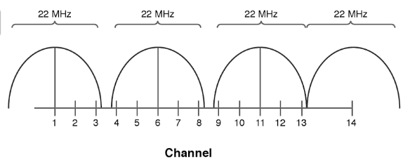
Nonoverlapping channels in the 2.4 GHz band: 1, 6, and 11
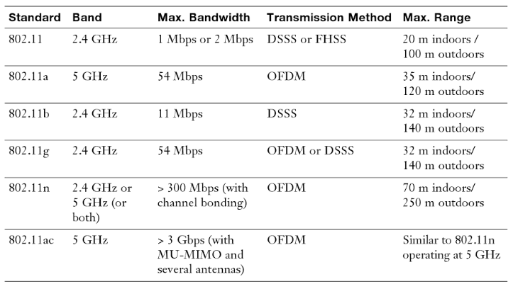
Characteristics of 802.11 standards
• Channels: a wireless channel is a specific range used for transmission. The channel is set on the WAP and devices will determine the best channel to use (although some end device wireless NICs allow the user to also set the channel which will be used). The range is 22MHz, so is quite a narrow band. The bands are numbered and each overlap slightly. Channel centre frequencies in the 2.4GHz range start with channel 1's centre frequency at 2.412 GHz, up to channel 14 at 2.484 GHz. Channel 14 is not supported in the U.S., though.
• Goodput: refers to the number of useful information bits that the network can deliver (not including overhead for the protocols being used). Goodput is the application-level throughput (i.e. the number of useful information bits delivered by the network to a certain destination per unit of time). The amount of data considered excludes protocol overhead bits as well as retransmitted data packets. This is related to the amount of time from the first bit of the first packet sent (or delivered) until the last bit of the last packet is delivered. For example, if a file is transferred, the goodput that the user experiences corresponds to the file size in bits divided by the file transfer time. The goodput is always lower than the throughput (the gross bit rate that is transferred physically), which generally is lower than network access connection speed (the channel capacity or bandwidth).
• Connection types
- 802.11a-ht: This refers to a wireless adapter with the Physical Type referred to as High Throughput (high successful data delivery) and using the 802.11a protocol.
- 802.11g-ht: This refers to a wireless adapter with the Physical Type referred to as High Throughput (high successful data delivery) and using the 802.11g protocol.
• Antenna placement: is very important when configuring the network as each WAP needs to be able to provide the greatest range possible with the transmission power selected. An antenna, as with an FM radio is a metal pole raised form the WAP allowing airborne transmission of the radio wave. It also is able to receive other radio transmissions and to pass these to the WAP for processing.
• Antenna types:
- Omnidirectional: an antenna that radiates equally in all directions.
- Unidirectional: signal coverage in a specified (one) direction. Can give you considerably more distance, or range, on your mobile signal. You have to know exactly where the mobile tower is that you're pointing at, but if you do and can shoot the unidirectional antenna straight at it, then you can reach a lot further – sometimes many kilometers.
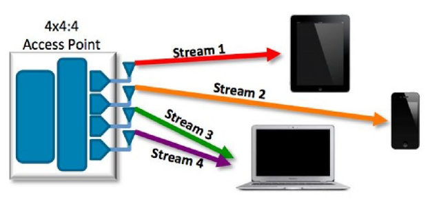
MU-MIMO - several streams communicating at the same time
• MIMO/MU-MIMO:
--> Multiple-input and multiple-output is a technique of using multiple antennas at both the transmitter and receiver to improve communication performance. It is an emerging technology that offers significant increases in speed and distance without a need for more transmission power. MIMO is used with 802.11n and with 4G technologies.
--> Multi-User MIMO uses a suite of technologies to send the signal from an array of different independent antennae and access points. MU-MIMO uses an extended version of the space-division multiple access algorithm to allow for separate signals to be combined and sent within the same radio band. When MIMO is used throughout a network with multiple users connecting to multiple antennas with multiple antennas, it is referred to as multiple-user multiple-input and multiple-output, or MUMIMO, seriously!
• Signal strength: is a measurement of radio transmission in dbm (decibels per metre). It is usually displayed to the end user as a percentage, or using 5 'bars' to grade the signal. The signal represents the strength to a specific connected endpoint (e.g. from the laptop through several wireless bridges and to a wireless router). The 'strength' is quite a general measurement and does not take into account the signalling technologies or algorithms used, only is a measure of strength and of dropped packets. Usually when the 'bar' rating drops to 2, wireless starts to become intermittent as dropped packets are quite frequent, so file transfer time will slow as 'goodput' quality reduces. To determine the strength of an antenna, we refer to its gain value. Consider a huge wireless tower emanating circular waves in all directions. If you could see these waves, you would see the data waves forming a sphere around the tower. The signals around the antenna flow equally in all directions (including up and down). An antenna that does this has a 0dbi gain value and is referred to as an isotropic antenna. The isotropic antenna rating provides a base point for measuring actual antenna strength. An antenna's gain value represents the difference between the 0dBi isotropic and the power of the antenna. For example, a wireless antenna advertised as a 15dBi antenna is 15 times stronger than the hypothetical isotropic antenna. The higher the decibel figure, the higher the gain. When looking at wireless antennas, remember that a higher gain value means stronger send and receive signals. In terms of performance, the general rule is that every 3dB of gain added doubles the effective power output of an antenna.
- Coverage: the area covered by the WAP where a usable connection can be made.
- Differences between device antennas: A wireless antenna is an integral part of overall wireless communication. Antennas come in many shapes and sizes, with each one designed for a specific purpose. Selecting the right antenna for a particular network implementation is a critical consideration and one that could ultimately decide how successful a wireless network will be. In addition, using the right antennas can save money on networking costs because you need fewer antennas and access points.Many small home network adapters and access points come with a nonupgradeable antenna, but higher-grade wireless devices require that you decide which antenna to use. Selecting an antenna takes careful planning and requires an understanding of what range and speed you need for a network. The antenna is designed to help wireless networks do the following:
• SSID broadcast: When a wireless device comes up, it will scan for service set identifiers (SSIDs) in its immediate area, which is basically a network name. In your own wireless LAN, you will likely want the devices to find the SSID that you are broadcasting, so you will make sure that it's enabled for broadcast. This is typically not a problem, since your broadcast should be stronger than any neighbor's broadcast because it is closer. The exception to this rule might be an office building that has many WAPs that are assigned many different SSIDs because they belong to the various tenants in the building. It is then possible that your neighbor's SSID broadcast could be stronger than yours, depending on where the clients are in the building. If users report that they are connected to a WAP but are still not able to see the resources they need or not able to authenticate to the network, you shouldverify that they are connected to your SSID and not your neighbor's. To enhance your security, you can also choose to set the WAP to disable the broadcasting of the SSID. In that case, users could connect to it only if they were told that it was there and what to type into the wireless configuration. This type of wireless security is not considered very strong and will only keep the most casual snoopers off your network. In fact, it may be more trouble than it's worth to disable your broadcast of your SSID because then you will have to tell anyone who wants to use the network where it is and train them how to connect to it. It really just depends on what your organizational policies dictate.
--> Multiple-input and multiple-output is a technique of using multiple antennas at both the transmitter and receiver to improve communication performance. It is an emerging technology that offers significant increases in speed and distance without a need for more transmission power. MIMO is used with 802.11n and with 4G technologies.
--> Multi-User MIMO uses a suite of technologies to send the signal from an array of different independent antennae and access points. MU-MIMO uses an extended version of the space-division multiple access algorithm to allow for separate signals to be combined and sent within the same radio band. When MIMO is used throughout a network with multiple users connecting to multiple antennas with multiple antennas, it is referred to as multiple-user multiple-input and multiple-output, or MUMIMO, seriously!
• Signal strength: is a measurement of radio transmission in dbm (decibels per metre). It is usually displayed to the end user as a percentage, or using 5 'bars' to grade the signal. The signal represents the strength to a specific connected endpoint (e.g. from the laptop through several wireless bridges and to a wireless router). The 'strength' is quite a general measurement and does not take into account the signalling technologies or algorithms used, only is a measure of strength and of dropped packets. Usually when the 'bar' rating drops to 2, wireless starts to become intermittent as dropped packets are quite frequent, so file transfer time will slow as 'goodput' quality reduces. To determine the strength of an antenna, we refer to its gain value. Consider a huge wireless tower emanating circular waves in all directions. If you could see these waves, you would see the data waves forming a sphere around the tower. The signals around the antenna flow equally in all directions (including up and down). An antenna that does this has a 0dbi gain value and is referred to as an isotropic antenna. The isotropic antenna rating provides a base point for measuring actual antenna strength. An antenna's gain value represents the difference between the 0dBi isotropic and the power of the antenna. For example, a wireless antenna advertised as a 15dBi antenna is 15 times stronger than the hypothetical isotropic antenna. The higher the decibel figure, the higher the gain. When looking at wireless antennas, remember that a higher gain value means stronger send and receive signals. In terms of performance, the general rule is that every 3dB of gain added doubles the effective power output of an antenna.
- Coverage: the area covered by the WAP where a usable connection can be made.
- Differences between device antennas: A wireless antenna is an integral part of overall wireless communication. Antennas come in many shapes and sizes, with each one designed for a specific purpose. Selecting the right antenna for a particular network implementation is a critical consideration and one that could ultimately decide how successful a wireless network will be. In addition, using the right antennas can save money on networking costs because you need fewer antennas and access points.Many small home network adapters and access points come with a nonupgradeable antenna, but higher-grade wireless devices require that you decide which antenna to use. Selecting an antenna takes careful planning and requires an understanding of what range and speed you need for a network. The antenna is designed to help wireless networks do the following:
- Work around obstacles
- Minimize the effects of interference
- Increase signal strength
- Focus the transmission, which can increase signal speed
• SSID broadcast: When a wireless device comes up, it will scan for service set identifiers (SSIDs) in its immediate area, which is basically a network name. In your own wireless LAN, you will likely want the devices to find the SSID that you are broadcasting, so you will make sure that it's enabled for broadcast. This is typically not a problem, since your broadcast should be stronger than any neighbor's broadcast because it is closer. The exception to this rule might be an office building that has many WAPs that are assigned many different SSIDs because they belong to the various tenants in the building. It is then possible that your neighbor's SSID broadcast could be stronger than yours, depending on where the clients are in the building. If users report that they are connected to a WAP but are still not able to see the resources they need or not able to authenticate to the network, you shouldverify that they are connected to your SSID and not your neighbor's. To enhance your security, you can also choose to set the WAP to disable the broadcasting of the SSID. In that case, users could connect to it only if they were told that it was there and what to type into the wireless configuration. This type of wireless security is not considered very strong and will only keep the most casual snoopers off your network. In fact, it may be more trouble than it's worth to disable your broadcast of your SSID because then you will have to tell anyone who wants to use the network where it is and train them how to connect to it. It really just depends on what your organizational policies dictate.
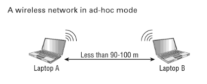
Adhoc network configuration: note the absence of an access point.
|
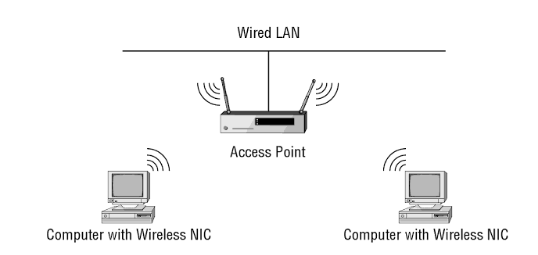
In infrastructure mode, wireless clients only communicate directly with the AP.
|
• Topologies:
- Adhoc: This is the easiest way to install wireless 802.11 devices. In this mode, the wireless NICs (or other devices) can communicate directly without the need for an AP. A good example of this is two laptops with wireless NICs installed. If both cards were set up to operate in ad hoc mode, they could connect and transfer files as long as the other network settings, like protocols, were set up to enable this as well. We'll also call this an independent basic service set (IBSS), which is created as soon as two wireless devices communicate. To set up a basic ad hoc wireless network, all you need are two wireless NICs and two computers. First (assuming they aren't built in), install the cards into the computers according to the manufacturer's directions. During the software installation, you'll be asked if you want to set up the NIC in ad hoc mode or infrastructure mode. For an ad hoc network, you would obviously go with the ad hoc mode setting. Once that's done, all you've got to do is bring the computers within range (90m-100m) of each other, and voila--they'll "see" each other and be able to connect to each other.
- Mesh: A wireless mesh network (WMN) is a communications network made up of radio nodes organized in a mesh topology. It is also a form of wireless ad hoc network. Wireless mesh networks often consist of mesh clients, mesh routers and gateways. The mesh clients are often laptops, cell phones and other wireless devices while the mesh routers forward traffic to and from the gateways which may, but need not, be connected to the Internet. The coverage area of the radio nodes working as a single network is sometimes called a mesh cloud. Access to this mesh cloud is dependent on the radio nodes working in harmony with each other to create a radio network. A mesh network is reliable and offers redundancy. When one node can no longer operate, the rest of the nodes can still communicate with each other, directly or through one or more intermediate nodes. Wireless mesh networks can self form and self heal. Wireless mesh networks can be implemented with various wireless technologies including 802.11, 802.15, 802.16, cellular technologies and need not be restricted to any one technology or protocol.
- Infrastructure: APs provide more permanent structure for the network. An infrastructure consists of one or more APs as well as a distribution system (that is, a wired network) behind the APs that tie the wireless network to the wired network.
• Mobile devices: You will find 802.11 wireless functionality in almost any device these days.
- Cell phones: Our mobile phones certainly have a cellular or mobile connectivity, but you also have the ability to turn on 802.11.
- Laptops: Almost all of our laptops have 802.11 wireless built into them these days, but if you have an older laptop, or it doesn’t have a wireless adapter, you could always use an external adapter and plug into a USB interface.
- Tablets: Our tablets are using 802.11 almost exclusively to provide networking.
- Gaming devices: And our gaming devices, even these days, with our Xboxes and PlayStations, are all using wireless to be able to communicate across those gaming networks.
- Media devices: We even have specialized media devices that connect to our televisions, and they’re pulling in information and streaming media from many different providers and putting it right into the HDMI ports on our television.
