4 - Troubleshooting
- 4.1 Given a scenario, implement the following network troubleshooting methodology.
- 4.2 Given a scenario, analyze and interpret the output of troubleshooting tools.
- 4.3 Given a scenario, troubleshoot and resolve common wireless issues.
- 4.4 Given a scenario, troubleshoot and resolve common copper cable issues.
- 4.5 Given a scenario, troubleshoot and resolve common fiber cable issues.
- 4.6 Given a scenario, troubleshoot and resolve common network issues.
- 4.7 Given a scenario, troubleshoot and resolve common security issues.
- 4.8 Given a scenario, troubleshoot and resolve common WAN issues.
4.1 Given a scenario, implement the following
network troubleshooting methodology
The Network+ Troubleshooting Model
There are seven stages in the CompTIA Network+ troubleshooting model.
1. Identify the problem. This stage includes:
• Gathering information
• Duplicating the problem, if possible
• Questioning users to gain experiential information
• Identifying the symptoms
• Determining if anything has changed
• Approaching multiple problems individually
2. Establish a theory of probable cause. This stage includes:
• Questioning the obvious
• Considering multiple approaches, such as examining the OSI model from top to bottom and bottom to top and dividing and conquering
3. Test the theory to determine the cause.
a. When the theory is confirmed, determine the next steps to resolve the problem.
b. If the theory is not confirmed, establish a new theory or escalate the issue.
4. Establish a plan of action to resolve the problem, while identifying the potential effects of your plan.
5. Implement the solution, or escalate the issue.
6. Verify full system functionality and, if applicable, implement preventative measures.
7. Document your findings, actions, and the outcomes.
4.2 Given a scenario, analyze and interpret the
output of troubleshooting tools
• Command line tools:
|
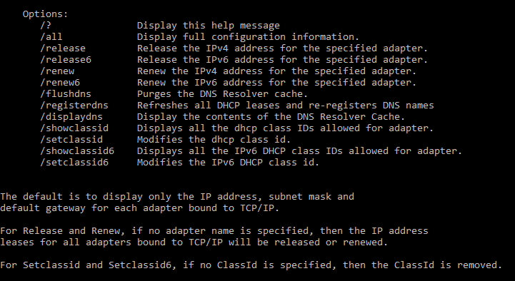
- ipconfig: The ipconfig command provides you with network information for each network adapter. It also displays connection-specific DNS suffix, IP address, subnet mask, and default gateway information. Must be run from a command line. To display additional information about a computer's IP configuration, use the command ipconfig /all command. The ipconfig /all command provides you with detailed network information for each network adapter, such as Domain Name System (DNS) server IP addresses, DHCP lease information, MAC address, and adapter hardware description. The ipconfig command is supported on all Windows server systems and client systems.
|
ipconfig switches:
|
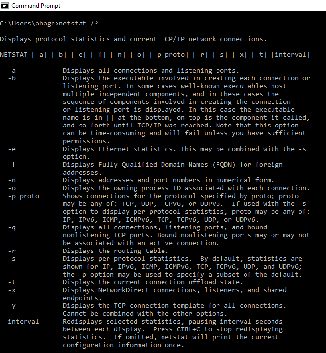
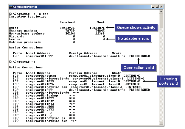
- netstat: The netstat, or network status command, displays a list of network services, connection information, and statuses. The NETSTAT utility shows the status of each active network connection. NETSTAT will display statistics for both TCP and UDP, including protocol, local address, foreign address, and the TCP connection state. Because UDP is connectionless, no connection information will be shown for UDP packets. The netstat –r command displays extensive routing table information for troubleshooting. NETSTAT is a versatile troubleshooting tool that can serve several functions. You can:
- Use NETSTAT to find out if a TCP/IP-based program, such as SMTP or FTP, is listening on the expected port. If not, the system might need to be restarted.
- Check statistics to see if the connection is good. If there is a bad connection, this usually means there are no bytes in the send or receive queues.
- Use statistics to check network adapter error counts. If the error count is high, it could be a problem with the card, or could indicate generally high network traffic.
- Use NETSTAT to display routing tables and check for network routing problems.
netstat switches:
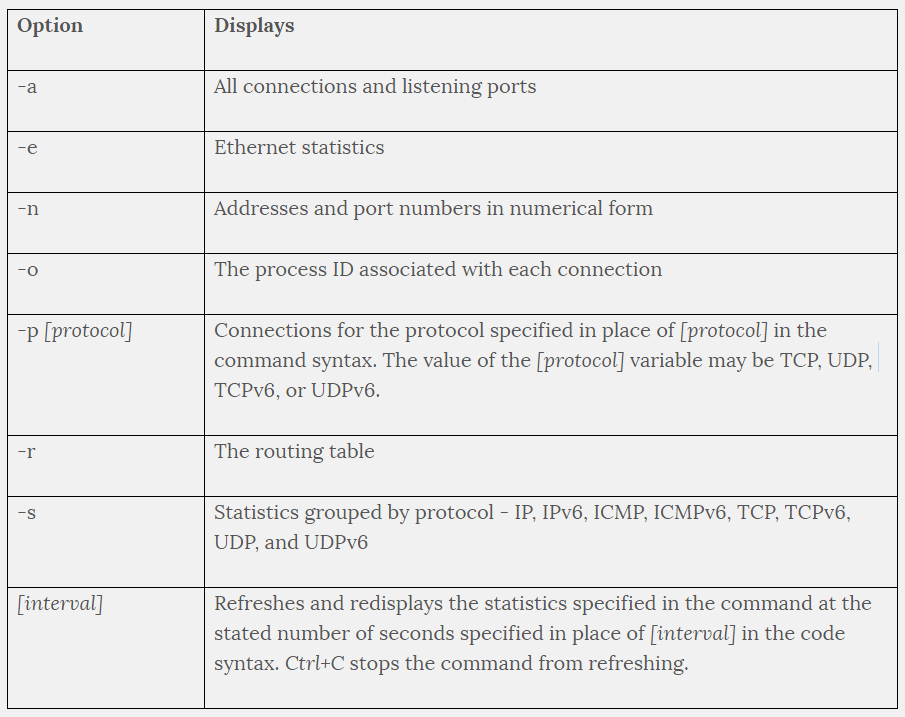
There are several options available to use with the NETSTAT command.
|
|
- ifconfig: The ifconfig command in Linux is analogous to the ipconfig command.
|
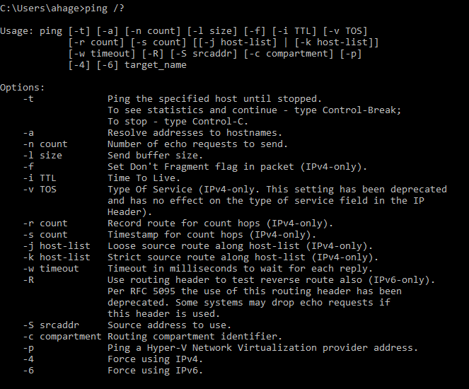
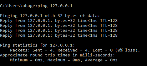
- ping/ping6/ping -6: To use ping with IPv6 addresses, you would use the ping -6 command. On a Linux machine, you would use ping6. Use the ping utility as an initial step in diagnosing general connectivity problems. To use ping with IPv6 addresses, use ping -6 for Windows or ping6 for Linux.The steps can include:
When you ping a computer, it will respond with one of the following responses:
|
ping switches:
ping loopback address;
|
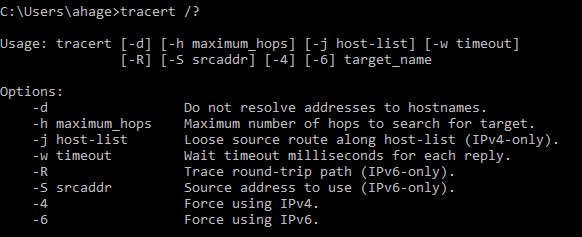
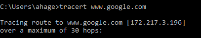
- tracert/tracert -6/traceroute6/traceroute -6: The tracert command determines the route data takes to get to a particular destination. On Windows, use the tracert command to print the route packets trace to a remote host. On a UNIX or Linux system, if you cannot connect to a particular remote host, you can use traceroute or traceroute6 for IPv6, to determine where the communication fails. Issue atraceroute command from the local machine to see how far the trace gets before you receive an error message. Using the IP address of the last successful connection, you will know where to begin troubleshooting the problem, and potentially even pinpoint a specific failed device. On Windows computers, the tracert or tracert -6 for IPv6, utility provides similar functionality. The maximum default number of hops for a traceroute or tracert is 30. You can specify a higher number using a command line switch and the number of hops you wish to use for the trace.
Sample tracert output
|
tracert switches:
tracert www.google.com
|
- nbtstat: the NBTSTAT utility is a Windows command that is unique because it displays NetBIOS information that isn’t available with other Transmission Control Protocol/Internet Protocol (TCP/IP) utilities.
nslookup
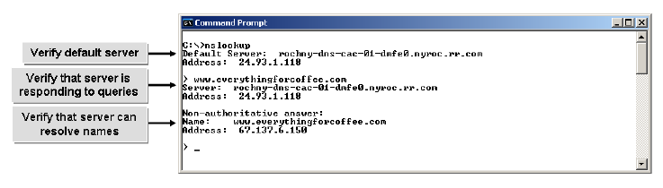
- nslookup: The nslookup utility is used to test and troubleshoot domain name servers. Nslookup has two modes: the interactive mode enables you to query name servers for information about hosts and domains, or to print a list of hosts in a domain. The non-interactive mode prints only the name and requested details for one host or domain. The non-interactive mode is useful for a single query. You can use nslookup to display information about DNS servers. You can verify that:
The syntax for the nslookup command is nslookup [-option ...] [computer-to-find | -[server]].
What service is working correctly if your nslookup <remote hostname> command returns an IP address associated with the name (remote host) that you supplied to the command? Domain Name System (DNS). The nslookup command, nslookup <remote hostname>, tells you that DNS is working correctly.
- The system is configured with the correct DNS server.
- The server is responding to requests.
- The entries on the server are correct.
- And, the DNS server can communicate with other servers in the DNS hierarchy to resolve names.
The syntax for the nslookup command is nslookup [-option ...] [computer-to-find | -[server]].
- To enter the interactive mode of nslookup, type nslookup without any arguments at a command prompt, or use only a hyphen as the first argument and specify a domain name server in the second. The default DNS name server will be used if you do not enter anything for the second argument.
- To use the non-interactive mode, in the first argument, enter the name or IP address of the computer you want to look up. In the second argument, enter the name or IP address of a domain name server. The default DNS name server will be used if you do not enter anything for the second argument.
What service is working correctly if your nslookup <remote hostname> command returns an IP address associated with the name (remote host) that you supplied to the command? Domain Name System (DNS). The nslookup command, nslookup <remote hostname>, tells you that DNS is working correctly.
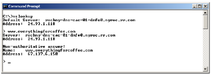
If an nslookup command returns information that includes a non-authoritative answer, what does that mean?
It means that the answer comes from a DNS server that isn’t authoritative for that domain.
|
- arp: The arp command displays the current entries in the ARP table. The Address Resolution Protocol (ARP) cache is a table used for maintaining the correlation between each MAC address and its corresponding IP address. The arp utility supports the Address Resolution Protocol (ARP) service of the TCP/IP protocol suite. It enables an administrator to view the ARP cache and add or delete cache entries. It is also used to locate a node's hardware address. Any added entry becomes permanent until it is deleted or the device is shut down. The ARP cache is a table used for maintaining the correlation between each media access control (MAC) address and its corresponding IP address. To reduce the number of address resolution requests, a client normally has all addresses resolved in the cache for a short period of time. The ARP cache is of a finite size; if no limit is specified, all incomplete and obsolete entries of unused devices will accumulate in the cache. The ARP cache is, therefore, periodically flushed of all entries to free up memory. arp can be used both to help troubleshoot duplicate IP address problems and to diagnose why a workstation cannot connect to a specific host. If a host is reachable from one workstation but not from another, you can use the arp command on both workstations to display the current entries in the ARP table. If the MAC address on the problem workstation does not match the correct MAC address, you can use arp to delete the incorrect entry. arp can be used in conjunction with ping to troubleshoot more complex network problems. If you ping a host on the network and there is no reply, the host may not necessarily be unavailable. The increased use of firewalls today can prevent a ping from returning accurate information. Instead, you can use the arp command to find the host by the MAC address and bypass the IP address resolution.
|
arp switches:
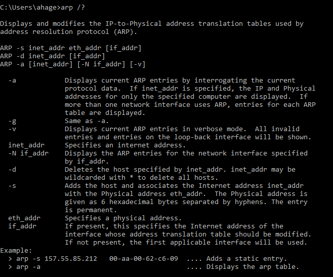
On both UNIX and Windows systems, the arp -a command will return a tabular listing of all ARP entries in the node's ARP cache. You can refer to online MAC address lookup tables to identify an address on a switch, in network command results, or in the ARP cache that you don’t think belongs on your network. Identifying the MAC address helps you identify the manufacturer of the device to help you narrow down the device you are looking for and remove it from your network.
|
- mac address lookup table: A switch listens to the transmissions of all of the nodes plugged into its ports. It learns the MAC addresses of each of the nodes and puts those MAC addresses into a table in memory. The table associates each MAC address with the port that it is plugged into. This table is called a MAC table or content addressable memory (CAM) table. When a node sends a frame to another node, the switch examines the Ethernet header for the destination MAC address. It refers to its MAC table to see which port it must forward the frame out of. It does not repeat the frame out any other port except the one that is required. In this way, conversations are limited to the nodes involved. If the switch receives a frame that has an unknown unicast (the address is not in the MAC table), multicast, or a broadcast destination MAC address, the switch will flood the frame out all ports except for the port that it received the frame from.
|
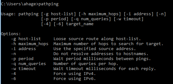
- pathping: The pathping command provides information about latency and packet loss on a network. pathping combines the functionality of the ping and tracert commands. Similar to ping, pathping sends multiple ICMP echo request messages to each router between two hosts over a period of time, and then displays results based on the number of packets returned by each router. It is similar to tracert as it identifies the routers that are on the path. In the output, it also displays the path to the remote host over a maximum of 30 hops. In addition, it displays details of packet transfer between the hosts in a time span of over 25 seconds, and the system names and their IP addresses. pathping can be used to isolate a router or subnet with issues as it can display the degree of packet loss at any given router or link. Is exclusive to Windows OS. The mtr command in Linus is equivalent to the pathping command, having the functionality of both the ping and the traceroute commands.
|
pathping switches:
|
• Line testers: A line tester, also called a cable tester, is not a certifier. A line tester is an electrical instrument that verifies if a signal is transmitted by a cable. A simple cable tester will determine whether a cable has an end-to-end connection and can detect shorts or opens, but cannot certify the cable for transmission quality, which is the cable installer's responsibility. Cable testers can differ based on their intended purpose.
• Certifiers: A cable certifier allows you to perform tests, such as cable testing and validity testing. It can detect shorts and crosstalk on a cable, test for the cable type and whether a cable is straight-through or crossover, and check if the NIC is functioning and at what speed: half or full duplex. A network cable certifier tests transmission speed and performance. A certification tester determines whether a cable meets specific ISO or TIA standards (CAT5e, CAT6, or CAT7). It should be used if a network is wired with both copper and fiber.
• Multimeter: A multimeter, also known as a volt/ohm meter, is an electronic measuring instrument that takes electrical measurements such as voltage, current, and resistance. A multimeter can be a handheld device for field service work or a bench-top model for in-house troubleshooting.
• Cable tester: A cable tester, also called a line tester, is an electrical instrument that verifies if a signal is transmitted by a cable. A simple cable tester will determine whether a cable has an end-to-end connection and can detect shorts or opens, but cannot certify the cable for transmission quality, which is the cable installer's responsibility. Cable testers can differ based on their intended purpose.
• Light meter: Light meters, also known as optical power meters, are devices used to measure the power in an optical signal. A typical light meter consists of a calibrated sensor, measuring amplifier, and display. The sensor primarily consists of a photodiode selected for the appropriate range of wavelengths and power levels. The display will show the measured optical power and set wavelength. A traditional light meter responds to a broad spectrum of light, and the user sets the wavelength to test. If there are other spurious wavelengths present, then wrong readings can result.
• Toner probe: The toner probe emits a tone when it detects a signal in a pair of wires. It’s used to trace and locate voice, audio, and video signals on a network. A tone generator is a device that sends an electrical signal through one pair of UTP wires. A tone locator or a tone probe is a device that emits an audible tone when it detects a signal in a pair of wires. Tone generators and tone locators are most commonly used on telephone systems to trace wire pairs. A digital toner and toner probe traces and locates voice, audio, and video cabling on a network. In addition to confirming the cable location, a toner and probe can verify continuity and detect faults. Do not confuse tone generators and tone locators with cable testers. Tone generators and tone locators can only help you differentiate between different UTP cables. To locate a cable in a group of cables, connect the tone generator to the copper ends of the wires; then move the tone locator over the group of cables. A soft beeping tone indicates that you are close to the correct wire set; when the beeping is loudest, you have found the cable.
• Speed test sites: A speed test site is a web service that measures the bandwidth (speed) and latency of a visitor's Internet connection. Tests typically measure the data rate for downloads and the upload data rate.
• Looking glass sites: A Looking Glass site is a web server that allows external users to get a look at routing and network behavior as it originates from the remote network. A looking glass site accesses a remote router and performs commands allowing a view of the IP and BGP route tables.The information is then presented to the user. Looking Glasses sites are used for verifying routing between providers, and for verifying that routes are propagating correctly across the Internet.
• WiFi analyzer: A wireless tester, or a WiFi analyzer, is a Wi-Fi spectrum analyzer used to detect devices and points of interference, as well as analyze and troubleshoot network issues on a WLAN or other wireless networks. Like network analyzers, wireless testers give an overview of the health of a WLAN in one central location, enabling technicians to troubleshoot problems efficiently.
• Protocol analyzer: A protocol analyzer, or a network analyzer, is diagnostic software that can examine and display data packets that are being transmitted over a network. It can examine packets from protocols that operate in the Physical, Data Link, Network, and Transport layers of the OSI model. You cannot gather info from the Application layer.
4.3 Given a scenario, troubleshoot and resolve common wireless issues
• Signal loss: signal loss can be caused by near-end crosstalk (when two cables run in parallel and the signal of one cable interferes with the other), or crossed or crushed wire pairs in twisted pair cabling. You should test with cable testers from both ends of the cable and correct any crossed or crushed wires. Verify that the cable is terminated properly and that the twists in the pairs of wires are maintained.
• Interference:
• Overlapping channels: Wi-Fi channels other than 1, 6, and 11 in the U.S. They are far away enough in frequency that they do not overlap. If you select channel 2, for example, channel 1 overlaps with it and your performance is decreased. There’s usually a two to three channel overlap in Wi-Fi signals; therefore, it’s generally safe to use channels 1, 6, and 11 in the U.S. If you are experiencing very slow speeds or no connectivity due to congested or overlapping channels, you should try to log into your router and manually change the channel the wireless router is operating on. Some channels can be crowded based on your physical location or receive interference based on their closeness to another channel.
- Mismatched channels
• Signal-to-noise ratio; When discussing electromagnetic interference (EMI) that disrupts a signal, the signal-to-noise ratio decreases as the transmission distance increases.
• Device saturation: A device is said to be saturated or has reached saturation when its percent utilization is close to 100.
• Bandwidth saturation:
• Untested updates: Another issue that could affect connectivity are untested updates to the wireless devices. As with updates on any other part of your network, you should test any updates to your wireless routers and devices before deploying the updates on a wide scale.
• Wrong SSID: A mismatched or incorrect SSID is likely the first issue to check. If the user’s computer is functioning normally in all other respects, make sure the SSID isn't different than the wireless network's.
• Power levels: You could also check to make sure that the power level on the WAP is set at the correct power level. If the WAP is not close to the device, power levels may be too low to bring signal to the device. Set the power level to 50% and make small incremental changes to find a good balance of power and coverage.
• Open networks: An open network is one that requires no password to connect to WiFi services. This is a major security violation and should never occur, especially in a corporate environment.
• Rogue access point: A wireless access point that is added to a network without the administrator’s consent or knowledge is considered a rogue access point. These are usually installed by employees who want wireless access to the network when no wireless access is available. Rogue access points can also be used as an evil twin. An evil twin operates outside of the organization’s network and receives beacons transmitted by the legitimate network with the intent of gaining access to the organization’s network by unauthorized users. What should you look for on a network if your primary WAP mysteriously begins to experience interference? A rogue access point.
• Wrong antenna type: Installing the wrong antenna type can make your Wi-Fi signal not reach far enough or it can make it so that the signal can be picked up outside the area you intend your network to reach. The range covered depends on the access point type (802.11b, g, or n) and the type of antenna connected to it. The standard antenna that comes with an 802.11g AP can usually reach about 100 meters. However, if a semi-parabolic antenna is installed, the same AP can often reach as far as 20 miles. Replace the wrong antenna type with the correct one. You can also use directional antennas to improve the distance the AP can reach without going outside of the desired area you want covered.
• Incompatibilities: Wireless devices won't connect if the settings on the wireless device are not compatible with the clients. Check the configuration of the wireless modem by accessing the web admin interface. Verify that the clients can support the same configuration. If not, identify the configuration, such as the encryption type, supported on both the clients and the server and apply the same on the wireless device and the client systems.
• Wrong encryption: If the encryption types between two devices (access point and client) do not match, no connection is established. Similarly, if different encryption keys are used between two devices, they cannot negotiate key information for verification and decryption in order to initiate communication.
• Bounce: low or no connectivity caused by signals from a device bouncing off obstructions, causing signals to not be received by a device. While all problem sources (wrong encryption, device/setting incompatibilities, wrong antenna type) would cause low or no connectivity for a device within a wireless network, bounce is the only one caused by signals from a device bouncing off obstructions, causing signals to not be received by a device.
• MIMO: Multiple input, multiple output (MIMO) uses multiplexing to increase wireless network range and bandwidth.
• AP placement: it is important to take into consideration the coverage area, physical obstacles, and number of users for AP placement. When determining the placement of wireless access points, you would not consider whether the users could visibly see the wireless access point. In fact, it may be advantageous both asthetically and for security purposes not to show individuals where the WAP is physically located.
• AP configurations: Tips for Troubleshooting Access Point (AP) Configuration Issues
• Environmental factors: Cubicle partitions would not interfere with wireless signals. However, many physical environmental factors can have an impact on signal strength. Signal strength can be lost when the signal encounters objects such as concrete walls, window film, or metal studs.
- Concrete walls
- Window film
- Metal studs
• Wireless standard related issues:
- Throughput:
- Frequency:
- Channels: congested channel:
• Interference:
- Symptoms: Crackling, humming, and static are all signs of interference. Additionally, low throughput, network degradation, and poor voice quality are also symptoms of interference.
- Causes: RF interference can be caused by a number of devices including cordless phones, Bluetooth devices, cameras, paging systems, unauthorized access points, and clients in the ad-hoc mode.
- Resolution: Remove or avoid environmental interferences as much as possible. This may simply entail turning off competing devices or relocating them. Ensure that there is adequate LAN coverage. To resolve problems proactively, test areas prior to deployment using tools such as spectrum analyzers.
• Overlapping channels: Wi-Fi channels other than 1, 6, and 11 in the U.S. They are far away enough in frequency that they do not overlap. If you select channel 2, for example, channel 1 overlaps with it and your performance is decreased. There’s usually a two to three channel overlap in Wi-Fi signals; therefore, it’s generally safe to use channels 1, 6, and 11 in the U.S. If you are experiencing very slow speeds or no connectivity due to congested or overlapping channels, you should try to log into your router and manually change the channel the wireless router is operating on. Some channels can be crowded based on your physical location or receive interference based on their closeness to another channel.
- Mismatched channels
• Signal-to-noise ratio; When discussing electromagnetic interference (EMI) that disrupts a signal, the signal-to-noise ratio decreases as the transmission distance increases.
• Device saturation: A device is said to be saturated or has reached saturation when its percent utilization is close to 100.
• Bandwidth saturation:
- Symptoms: Very slow speed or no connectivity.
- Causes: On a wireless network, you can only have a certain number of devices connected before performance begins deteriorating. When you reach the device saturation limit, transmissions will be lost and need to be re-sent, thus decreasing the throughput to the device. Bandwidth saturation on wireless networks can also be reached if you have a lot of devices connected, or a device is transferring a large volume of data.
- Resolution: Replace the WAP with one that provides better bandwidth, or add another WAP to support the needed traffic demands. Investigate to see if some device could use a wired connection instead.
• Untested updates: Another issue that could affect connectivity are untested updates to the wireless devices. As with updates on any other part of your network, you should test any updates to your wireless routers and devices before deploying the updates on a wide scale.
• Wrong SSID: A mismatched or incorrect SSID is likely the first issue to check. If the user’s computer is functioning normally in all other respects, make sure the SSID isn't different than the wireless network's.
• Power levels: You could also check to make sure that the power level on the WAP is set at the correct power level. If the WAP is not close to the device, power levels may be too low to bring signal to the device. Set the power level to 50% and make small incremental changes to find a good balance of power and coverage.
• Open networks: An open network is one that requires no password to connect to WiFi services. This is a major security violation and should never occur, especially in a corporate environment.
• Rogue access point: A wireless access point that is added to a network without the administrator’s consent or knowledge is considered a rogue access point. These are usually installed by employees who want wireless access to the network when no wireless access is available. Rogue access points can also be used as an evil twin. An evil twin operates outside of the organization’s network and receives beacons transmitted by the legitimate network with the intent of gaining access to the organization’s network by unauthorized users. What should you look for on a network if your primary WAP mysteriously begins to experience interference? A rogue access point.
• Wrong antenna type: Installing the wrong antenna type can make your Wi-Fi signal not reach far enough or it can make it so that the signal can be picked up outside the area you intend your network to reach. The range covered depends on the access point type (802.11b, g, or n) and the type of antenna connected to it. The standard antenna that comes with an 802.11g AP can usually reach about 100 meters. However, if a semi-parabolic antenna is installed, the same AP can often reach as far as 20 miles. Replace the wrong antenna type with the correct one. You can also use directional antennas to improve the distance the AP can reach without going outside of the desired area you want covered.
• Incompatibilities: Wireless devices won't connect if the settings on the wireless device are not compatible with the clients. Check the configuration of the wireless modem by accessing the web admin interface. Verify that the clients can support the same configuration. If not, identify the configuration, such as the encryption type, supported on both the clients and the server and apply the same on the wireless device and the client systems.
• Wrong encryption: If the encryption types between two devices (access point and client) do not match, no connection is established. Similarly, if different encryption keys are used between two devices, they cannot negotiate key information for verification and decryption in order to initiate communication.
• Bounce: low or no connectivity caused by signals from a device bouncing off obstructions, causing signals to not be received by a device. While all problem sources (wrong encryption, device/setting incompatibilities, wrong antenna type) would cause low or no connectivity for a device within a wireless network, bounce is the only one caused by signals from a device bouncing off obstructions, causing signals to not be received by a device.
• MIMO: Multiple input, multiple output (MIMO) uses multiplexing to increase wireless network range and bandwidth.
• AP placement: it is important to take into consideration the coverage area, physical obstacles, and number of users for AP placement. When determining the placement of wireless access points, you would not consider whether the users could visibly see the wireless access point. In fact, it may be advantageous both asthetically and for security purposes not to show individuals where the WAP is physically located.
• AP configurations: Tips for Troubleshooting Access Point (AP) Configuration Issues
- Check the configuration of the wireless modem by accessing the web admin interface.
- Check the encryption type, SSID, and passphrase text that is specified and confirm that the wireless modem was rebooted after the configuration change.
- Ensure that the clients can also support the same encryption type.
- Verify that the same SSID and key phrase are defined in the network connection.
- Verify that the wireless receiver on the client is configured properly with the correct compatible drivers installed.
- Similarly, for a laptop, check that the wireless network adapter is functional and is turned on. If needed, update the device driver on the client systems.
- Check to see if any untested updates were applied to your wireless routers or devices. As with updates on any other part of your network, you should test any updates to your wireless routers and devices before deploying the updates on a wide scale. Troubleshooting a single update on a single device is much easier than troubleshooting it on an organization-wide basis.
- Determine whether the access point is stand-alone (thick) or controller based (thin). A thick AP is a stand-alone device so you will only have to check configuration settings for it. For a thin AP, it will also connect to a wireless LAN controller and will use the Lightweight Access Point Protocol (LWAPP), which controls multiple Wi-Fi WAPs and reduces time spent on configuring, monitoring, or troubleshooting large networks. The controller will need to be accessed to check configuration settings.
• Environmental factors: Cubicle partitions would not interfere with wireless signals. However, many physical environmental factors can have an impact on signal strength. Signal strength can be lost when the signal encounters objects such as concrete walls, window film, or metal studs.
- Concrete walls
- Window film
- Metal studs
• Wireless standard related issues:
- Throughput:
- Frequency:
- Symptoms: No connectivity.
- Causes: Devices must operate on the same frequency. For example, a device to communicate at 5 GHz frequency cannot communicate with one designed to communicate at 2.4 GHz.
- Channels: congested channel:
- Symptoms: Very slow speeds.
- Causes: Interference from neighboring wireless networks; congested network channels.
- Resolution: Many wireless routers are set to autoconfigure the same wireless channel. Try logging in to the router and manually change the channel the wireless router is operating on.
4.4 Given a scenario, troubleshoot and resolve common copper cable issues
• Shorts: When a cable is cut, it is shorted. Often the short involves bare wire coming in contact with other conductive surfaces.
• Opens: Cable and network professionals will sometimes refer to shorts as opens, referring to the fact that the electrical signal loop is open.
• Incorrect termination (mismatched standards): Verify that the cable is terminated properly and that the twists in the pairs of wires are maintained.
- Straight-through:
- Crossover:
• Cross-talk: Generally, crosstalk occurs when two cables run in parallel and the signal of one cable interferes with the other. Crosstalk can also be caused by crossed or crushed wire pairs in twisted pair cabling. Look for excessive cross-talk when testing a cable for a split pair. You should test with cable testers from both ends of the cable and correct any crossed or crushed wires. Verify that the cable is terminated properly and that the twists in the pairs of wires are maintained.
- Near end: Near-end crosstalk occurs more closely along the transmitting end of the cable. Often occurs in or near the terminating connector.
- Far end: Far-end crosstalk occurs at the other end of the cable from the transmitter that is causing the interference.
• EMI/RFI: Electromagnetic and radio-frequency interference can be caused by a number of devices including cordless phones, Bluetooth devices, cameras, paging systems, unauthorized access points, and clients in the ad-hoc mode. For a WAN connection, the distance of a WAN link, including all the networks and connections it may have to traverse, could make it more susceptible to interference, especially for DSL links that have practical distance limits, or radio transmissions that can be easily interfered with. To resolve such issues from EMI or RFI, remove or avoid environmental interferences as much as possible. This may simply entail turning off competing devices or relocating them. Ensure that there is adequate LAN coverage. To resolve problems proactively, test areas prior to deployment by using tools such as spectrum analyzers. While twisted pair wiring is effective in office environments in which the amount of electromagnetic interference (EMI) and radio frequency interference (RFI) are relatively low. In high-noise environments such as machine shops and hospital radiology departments, consider using fiber optic cabling, which is immune to EMI/RFI.
--> Electromagnetic interference (EMI) disrupts a signal. The signal-to-noise ratio decreases as the transmitting distance increases.
• Distance limitations: a possible cause of communication problems could be that cables are being run beyond their maximum supported distance. Check to ensure that the correct cables are used at the correct distances for the speeds you intend. If a cable run is too long, move to a more appropriate cable or consider reconfiguring your physical network to meet appropriate cable lengths.
• Attenuation/Db loss: the progressive degradation of signal as it travels across a network cable. Attenuation is the progressive degradation of a signal as it travels across a network medium. Some media types are more susceptible to attenuation than others. Attenuation can also occur when the cable length exceeds the recommended length. In case of wired networks, you would use shorter cable runs to fix this. In case of wireless networks, you would add more access points and signal boosters along the transmission path. Long cable length, poor connections, bad insulation, high level of crosstalk, or electro-magnetic interference (EMI) can all increase attenuation. Attenuation occurs when there is a degradation of signal strength, which results in slow responses from the network.
• Bad connector: if a cable has a bad connector, check and replace the faulty connectors. Verify that the cables are properly secured to the connectors and are properly crimped.
• Bad wiring: Review the wires and check that all are in good condition. Replace those that are not. You'll also want to check cable placement and look for sources of interference that could cause attenuation or DB loss and remove them if found.
• Split pairs: are among the most difficult to diagnose of wiring errors. When testing a cable, look for excessive crosstalk to detect a split pair. You have to use a certifier device to detect a split pair because a simple line tester isn’t sufficient for the job.
• Tx/Rx reverse: Example: You are attempting to connect two similar devices to each other. You connect one end of a Ethernet cable to the first device and the other to the second. However, the second device will not recognize the connection, even though both devices are fully operational. What is likely the problem? TX/RX reversed. It’s likely that the transmit (TX) and receive (RX) are reversed due to incorrect wiring layout, perhaps resulting in a straight-through cable. Incorrect terminations can cause intermittent problems with a network connections. Ensure that the correct cable type is used (crossover or straight-through). Straight-through cables (also referred to as patch cables) are used to connect unlike devices, such as computers to hubs or switches. All wire pairs are in the same order at each end of the cable. Crossover cables enable you to connect devices without using a hub or a switch. In a crossover cable, the transmit and receive lines are crossed to make them work like a loopback—a function that the switch does. Crossover cables are used to connect like devices, such as device to device, switch to switch, or router to router. In a crossover cable, the transmit conductor at one end is connected to the receive conductor at the other, allowing both devices to communicate simultaneously.
• Cable placement: The placement of your cable is almost as important as the type of cable that you use. Cable management is critical!
• Bad SFP/GBIC - cable or transceiver: A gigabit interface converter (GBIC) is a transceiver used to convert electrical signals into optical signals and vice versa. It is used as an interface for high-speed networking and to upgrade the network, without needing to replace all components in the motherboards. For instance, if different optical technologies are used, GBICs can be used to specifically configure that link on the network. Based on the wavelength of laser light generated within the GBIC generator, GBICs can be categorized into short-wave GBICs and long-wave GBICs. The short-wave GBIC is used for connecting devices that are between 0.5 meters and 500 meters apart. Meanwhile, the long-wave GBIC is used for connecting devices that are between 2 meters and 6 miles apart. A small form factor pluggable (SFP) transceiver is most commonly used in 2 Gbps and 4 Gbps Fibre Channel components to interconvert electrical signals and optical signals. Switcs are similar to GBICs in their architecture, but they allow higher port density than GBICs.
Example: You're receiving an error on a device's Gigabit interface converter (GBIC) and seeing that no communication is going through the device. It's possible the modules in the GBIC are corrupted or the cable is bad. What should you do to correct the issue? Check the cable and replace any faulty GBICs. You would check the cable and replace any faulty GBICs. While switching to SFP would allow the higher port density, that would not fix the issue in this case. GBICs are built specifically so you do not have to replace all the components in the motherboard for the device, especially when doing network upgrades. Switching to long-wave from short-wave would not have an effect on corrupted GBICs or bad cables.
• Opens: Cable and network professionals will sometimes refer to shorts as opens, referring to the fact that the electrical signal loop is open.
• Incorrect termination (mismatched standards): Verify that the cable is terminated properly and that the twists in the pairs of wires are maintained.
- Straight-through:
- Crossover:
• Cross-talk: Generally, crosstalk occurs when two cables run in parallel and the signal of one cable interferes with the other. Crosstalk can also be caused by crossed or crushed wire pairs in twisted pair cabling. Look for excessive cross-talk when testing a cable for a split pair. You should test with cable testers from both ends of the cable and correct any crossed or crushed wires. Verify that the cable is terminated properly and that the twists in the pairs of wires are maintained.
- Near end: Near-end crosstalk occurs more closely along the transmitting end of the cable. Often occurs in or near the terminating connector.
- Far end: Far-end crosstalk occurs at the other end of the cable from the transmitter that is causing the interference.
• EMI/RFI: Electromagnetic and radio-frequency interference can be caused by a number of devices including cordless phones, Bluetooth devices, cameras, paging systems, unauthorized access points, and clients in the ad-hoc mode. For a WAN connection, the distance of a WAN link, including all the networks and connections it may have to traverse, could make it more susceptible to interference, especially for DSL links that have practical distance limits, or radio transmissions that can be easily interfered with. To resolve such issues from EMI or RFI, remove or avoid environmental interferences as much as possible. This may simply entail turning off competing devices or relocating them. Ensure that there is adequate LAN coverage. To resolve problems proactively, test areas prior to deployment by using tools such as spectrum analyzers. While twisted pair wiring is effective in office environments in which the amount of electromagnetic interference (EMI) and radio frequency interference (RFI) are relatively low. In high-noise environments such as machine shops and hospital radiology departments, consider using fiber optic cabling, which is immune to EMI/RFI.
--> Electromagnetic interference (EMI) disrupts a signal. The signal-to-noise ratio decreases as the transmitting distance increases.
- Symptoms: Crackling, humming, and static are all signs of interference. Additionally, low throughput, network degradation, and poor voice quality are also symptoms of interference.
- Causes: RF interference can be caused by a number of devices including cordless phones, Bluetooth devices, cameras, paging systems, unauthorized access points, and clients in the ad-hoc mode.
- Resolution: Remove or avoid environmental interferences as much as possible. This may simply entail turning off competing devices or relocating them. Ensure that there is adequate LAN coverage. To resolve problems proactively, test areas prior to deployment using tools such as spectrum analyzers.
• Distance limitations: a possible cause of communication problems could be that cables are being run beyond their maximum supported distance. Check to ensure that the correct cables are used at the correct distances for the speeds you intend. If a cable run is too long, move to a more appropriate cable or consider reconfiguring your physical network to meet appropriate cable lengths.
• Attenuation/Db loss: the progressive degradation of signal as it travels across a network cable. Attenuation is the progressive degradation of a signal as it travels across a network medium. Some media types are more susceptible to attenuation than others. Attenuation can also occur when the cable length exceeds the recommended length. In case of wired networks, you would use shorter cable runs to fix this. In case of wireless networks, you would add more access points and signal boosters along the transmission path. Long cable length, poor connections, bad insulation, high level of crosstalk, or electro-magnetic interference (EMI) can all increase attenuation. Attenuation occurs when there is a degradation of signal strength, which results in slow responses from the network.
• Bad connector: if a cable has a bad connector, check and replace the faulty connectors. Verify that the cables are properly secured to the connectors and are properly crimped.
• Bad wiring: Review the wires and check that all are in good condition. Replace those that are not. You'll also want to check cable placement and look for sources of interference that could cause attenuation or DB loss and remove them if found.
• Split pairs: are among the most difficult to diagnose of wiring errors. When testing a cable, look for excessive crosstalk to detect a split pair. You have to use a certifier device to detect a split pair because a simple line tester isn’t sufficient for the job.
• Tx/Rx reverse: Example: You are attempting to connect two similar devices to each other. You connect one end of a Ethernet cable to the first device and the other to the second. However, the second device will not recognize the connection, even though both devices are fully operational. What is likely the problem? TX/RX reversed. It’s likely that the transmit (TX) and receive (RX) are reversed due to incorrect wiring layout, perhaps resulting in a straight-through cable. Incorrect terminations can cause intermittent problems with a network connections. Ensure that the correct cable type is used (crossover or straight-through). Straight-through cables (also referred to as patch cables) are used to connect unlike devices, such as computers to hubs or switches. All wire pairs are in the same order at each end of the cable. Crossover cables enable you to connect devices without using a hub or a switch. In a crossover cable, the transmit and receive lines are crossed to make them work like a loopback—a function that the switch does. Crossover cables are used to connect like devices, such as device to device, switch to switch, or router to router. In a crossover cable, the transmit conductor at one end is connected to the receive conductor at the other, allowing both devices to communicate simultaneously.
• Cable placement: The placement of your cable is almost as important as the type of cable that you use. Cable management is critical!
- Separate your fiber and copper. Copper bundles can crush the fiber.
- Centralize your wiring plant. Middle of the data center.
- Use structured cabling systems. Keep everything neat.
- Think about EMI and interference with copper cables. Avoid power cords, fluorescent lights, electrical cables, and fire prevention components.
- Test after installation. You can find most of your problems before use.
• Bad SFP/GBIC - cable or transceiver: A gigabit interface converter (GBIC) is a transceiver used to convert electrical signals into optical signals and vice versa. It is used as an interface for high-speed networking and to upgrade the network, without needing to replace all components in the motherboards. For instance, if different optical technologies are used, GBICs can be used to specifically configure that link on the network. Based on the wavelength of laser light generated within the GBIC generator, GBICs can be categorized into short-wave GBICs and long-wave GBICs. The short-wave GBIC is used for connecting devices that are between 0.5 meters and 500 meters apart. Meanwhile, the long-wave GBIC is used for connecting devices that are between 2 meters and 6 miles apart. A small form factor pluggable (SFP) transceiver is most commonly used in 2 Gbps and 4 Gbps Fibre Channel components to interconvert electrical signals and optical signals. Switcs are similar to GBICs in their architecture, but they allow higher port density than GBICs.
Example: You're receiving an error on a device's Gigabit interface converter (GBIC) and seeing that no communication is going through the device. It's possible the modules in the GBIC are corrupted or the cable is bad. What should you do to correct the issue? Check the cable and replace any faulty GBICs. You would check the cable and replace any faulty GBICs. While switching to SFP would allow the higher port density, that would not fix the issue in this case. GBICs are built specifically so you do not have to replace all the components in the motherboard for the device, especially when doing network upgrades. Switching to long-wave from short-wave would not have an effect on corrupted GBICs or bad cables.
4.5 Given a scenario, troubleshoot and resolve common fiber cable issues
In fiber networking, technicians use small form factor pluggable (SFPs) and gigabit interface converter (GBICs) to interface a network device motherboard of a switch, router, media converter, or similar device with a fiber optic networking cable.
• Attenuation/Db loss: One benefit of using fiber optic wiring over twisted pair copper wiring in network communications is that fiber optic cables have greatly reduced susceptibility to attenuation. However, attenuation can still be cause in fiber networks if the cable length exceeds the recommended length. Attenuation is a minimal concern, even over longer distances, with fiber networking. Signal loss or slow responses from the network could be caused by fiber type mismatch, connector mismatch, or wavelength mismatch. These cause a mismatch of the chosen light wavelength and the cable that conducts it. Because both the core and cladding of fiber optic cable are designed to be optimal for specific wavelengths, you do not want to mix and match the various cable types or connectors. To fix these issues, you would replace the mismatched fiber cables and terminations to ensure they use the same type. What type of device would you use to measure signal quality in a fiber optic line? OTDR. Optical Time-Domain Reflectometers (OTDRs) are a variation of TDR used specifically for fiber optic cabling to determine cabling issues.
• SFP/GBIC - cable mismatch: a cable mismatch would make the link go down, providing no connectivity. SFP is a different, smaller connector type than the older GBIC. If you are using an SFP cable for a GBIC transceiver (or vice versa), the network would not operate. Always make sure you have the right cable for each type of connector type.
• Bad SFP/GBIC - cable or transceiver: Bad SFPs or GBICs or cables to either transceiver would make the link go down, providing no connectivity. This is the same with a cable mismatch. SFP is a different, smaller connector type than the older GBIC. If you are using an SFP cable for a GBIC transceiver (or vice versa), the network would not operate. Always make sure you have the right cable for each type of connector type.
• Wavelength mismatch: A wavelength mismatch can occur when the provisioned value for wavelength does not match the supported wavelength. Signal loss or slow responses from the network could be caused by fiber type mismatch, connector mismatch, or wavelength mismatch. These cause a mismatch of the chosen light wavelength and the cable that conducts it. Because both the core and cladding of fiber optic cable are designed to be optimal for specific wavelengths, you do not want to mix and match the various cable types or connectors. To fix these issues, you would replace the mismatched fiber cables and terminations to ensure they use the same type.
• Fiber type mismatch: Signal loss or slow responses from the network could be caused by fiber type mismatch, connector mismatch, or wavelength mismatch. These cause a mismatch of the chosen light wavelength and the cable that conducts it. Because both the core and cladding of fiber optic cable are designed to be optimal for specific wavelengths, you do not want to mix and match the various cable types or connectors. To fix these issues, you would replace the mismatched fiber cables and terminations to ensure they use the same type.
• Dirty connectors: if your fiber signal is weak on a particular cable, but you find no breaks or physical interference problems you should check the cable connectors for obstructions or dirt. Dirty connectors that obscure the signal or the connection can result in a weak signal.
• Connector mismatch: if your fiber cable has no physical damage and you are sure that the connections are clean and free of debris, but there is still no signal. You have also checked the hardware on both ends and found it to be good. Then the most probable cause is mismatched connectors. Inspect both ends of the cable and be sure that all connectors are appropriate for the application and that they match.
• Bend radius limitations: Fiber cable has a bend radius limitation that when exceeded can cause less than optimal or no signal transmission. Other than cuts or other actual damage, look for bent cables. In troubleshooting fiber cable connections, other than physical damage, excessive bends can hinder signal transmission.
• Distance limitations:
4.6 Given a scenario, troubleshoot and resolve common network issues
• Incorrect IP configuration/default gateway:
--> Incorrect IP configuration: after resolving a user's IP address conflict you should investigate the conflicting address cause (the source of the IP address conflict).
--> Incorrect default gateway: if a user can operate on their own subnet (i.e. able to contact network printers and a file server located on their floor), but are unable to browse the internet or connect to a remote system on another floor, the user's default gateway is missing or incorrect. The default gateway is only important for traversing the nearest router, which is the default gateway.
• Broadcast storms/switching loop: If a network segment experiences frequent broadcast storms, to prevent them install a managed switch and enable Spanning Tree Protocol (STP).
• Duplicate IP: if a user receives a notification on his desktop that reads, “The system has detected an IP address conflict with another system on the network. The local interface has been disabled. More details are available in the system event log. Consult your network administrator to resolve the conflict.” The user contacts you, the network administrator, to resolve the problem. What do you do? Run ipconfig /renew on the user's computer to request a new IP address from the DHCP server.
• Speed and duplex mismatch: if you install a new server on your network and it cannot connect to the rest of the network, you should check the network interface controller’s speed and duplex settings and the corresponding switch port’s speed and duplex settings to be sure that they match. Port duplex mismatches are generally caused by configuration errors. They occur when the switch port and a device are configured to use a different set of duplex settings, or when both ends are set to auto negotiate the settings. Port duplex mismatches could cause late collisions, port alignment errors, and Frame Check Sequence (FCS) errors, but would not be responsible for complete signal loss.
• End-to-end connectivity: if a user’s computer checks out as functional, but cannot get a good network connection, then check the network cable for end-to-end connectivity with a cable tester.
• Incorrect VLAN assignment: check the VLAN ID configuration on the switch port.
• Hardware failure: if a user's computer cannot connect to the LAN and you determine that the onboard network interface controller (NIC) has gone bad, you should disable the onboard NIC (and label it as bad) and install a new NIC into an open slot on the motherboard.
• Misconfigured DHCP: example: One of your colleagues recently replaced several of your old servers with new ones. Your colleague also had to set up all network services on the new servers. The next day you arrive at work and find out that no one in the office can connect to the network. What do you suspect is the problem? A miconfigured DHCP server. The likely problem is a misconfigured DHCP server because no one can connect to the network. Check the DHCP server setup.
• Misconfigured DNS: example: No one on your network can connect to the Internet, but you realize that you can connect to sites by IP address, but not by World Wide Web name. What do you do from your computer to confirm your suspicion? Run ipconfig /all and check the DNS settings.
• Incorrect interface/interface misconfiguration: Incorrect interfaces or interface misconfigurations can cause devices to stop communicating with each other. The first step in determining the cause of devices that you believe are not communicating with each other is to use the ping command to verify the state and connectivity of the devices. You would begin by using the ping command to determine if there is connectivity between devices. The ping command is used to verify the network connectivity of a device, and also to check to see if the target device is active. It verifies the IP address, host name, and reachability of the remote device by using and listening for echo replies. As there are many potential causes of two devices not communicating, you may not have any error messages to use for additional information. Each device should have a unique Internet protocol (IP) address, not a similar one. Two devices not communicating can be caused by a device sharing an IP address with another. Resolution of the misconfiguration will depend on the problem. If a network is running a rogue dynamic host configuration protocol (DHCP) server, for example, two devices could have been leased the same IP address. Check TCP/IP configuration info by using ipconfig /all on Windows devices, and ifconfig on Linux/UNIX/Mac devices. After confirming the issue, troubleshoot DHCP. It could also be the case that a static IP address was entered incorrectly. Check IP addresses, and empty the address resolution protocol (ARP) cache on both devices. Check the subnet mask on both devices, and if an incorrect subnet is mask is found, change it to a correct one and test connectivity.
• Cable placement:
• Interface errors: If there is no connectivity between devices, a device is generating an error message, or the WAN connection is down, the device may be misconfigured or it, or another device, is failing. For WAN connections, there may be issues such as a protocol mismatch between the two routers, an improperly configured data communications equipment (DCE)/data termination equipment (DTE) relationship, or there might be PPP authentication mismatch between the two sides. To resolve these issues, review system messages for the device, if any, to see if there is information that indicates what the issue is. You can use utilities to look for errors such as cyclic redundancy checking (CRC) errors, collisions, and frame errors. The exact resolution is based on the information found within the error.
• Simultaneous wired/wireless connections: Unpredictable or ambiguous packet routing would be caused by packets being sent on more than one connection, not just one. If both the wired and wireless connections are on the same subnet then either one connection will have a lower route cost than the other, or routes will be ambiguous and unpredictable. For example, if your wired LAN connection has a lower cost, the wireless connection will always be used whenever it is active. However, if both connections have the same cost, some packets may be routed to the wired LAN and others to the wireless network. To resolve this specific issue, you would need to change the subnet of one of the networks. Other issues can occur when having multiple connections on a single device. For example, if you are connected to both, you may want to use the wired connection for its higher transfer rate but the wireless connection may be the one used. If a device is connected using the wired connection and then the user disconnects it to move to another location where they will rely on the wireless connection, they will lose their network connection while the device switches from the disconnected NIC to the wireless adapter. Normally this only results in a brief interruption of network connectivity. If the user was connected to an application, it may need to be closed and reopened for it to use the new connection. Users should be educated on how the two connections work when both are available and what happens when one is added or removed.
• Discovering neighboring devices/nodes: Network discovery is a method for devices to find each other on the network. This is usually a configuration option as it can lead to some security issues, mostly on public networks. When not working, devices typically can be pinged but cannot be connected to. If network discovery is used but not functioning, then the first step to take is to make sure that the option has been enabled. Check network connectivity in general to make sure there isn't another issue causing the problem. Typically there are certain services that need to be running in order for the network discovery to work properly. For example, for Windows these typically include: DNS Client, SSDP Discovery, UPnP Device Host, and Function Discovery Resource Publication services. For your system, verify that the required services are running. Some security applications such as firewalls may interfere with network discovery. Research what traffic needs to be allowed and determine if your firewall or other security application is causing the issue.
• Power failure/power anomalies: There are many ways to mitigate a downed network due to power or hardware failure, but in terms of power failure, use cable modems and other network devices with battery- backed power supplies to ensure that there is uninterrupted service of several hours in case of local power failures.
• MTU/MTU black hole: A black hole in a network is where traffic is discarded, blocked, or dropped without alerting the sender or receiver that it did not reach its intended destination. Because no alerts are received by either end, the black hole can only be detected by monitoring the lost traffic, hence the name. When sending traffic across a network, computers use a maximum transmission unit (MTU) setting, which dictates the size of the largest frame the network interface can send across the network. When a network router receives a packet larger than the Maximum Transfer Unit (MTU) of the next network segment, and that packet's IP layer "don't fragment" bit is flagged, the router should send an ICMP destination unreachable message back to the sending host. When this does not happen, packets can be dropped, causing a variety of errors that will vary with the application that is communicating over the failed link. An MTU black hole occurs when the ICMP message doesn't reach the sending host to inform it that it needs to adjust its MTU.
• Missing IP routes: If a router is sending packets using an invalid path, the router settings are incorrect. You should check the router settings and protocols. Missing IP routes are either the result of missing or misconfigured routing protocols, or an unconfigured or misconfigured default gateway address. Check and change the router setting and reboot the router for the changes to take effect.
• NIC teaming misconfiguration: NIC Teaming is the process of combining multiple network cards together to enhance performance and redundancy. If an administrator misconfigures a NIC team so that it ends up being not one aggregate link (also known as a trunk), but several parallel links, or if something happens to the hardware that causes the aggregate to break apart, any broadcast or multicast would cause an instant broadcast storm, causing the network to be overwhelmed by constant broadcast traffic. To solve this issue, an administrator would configure “active” and “passive” features of the Link Aggregation Control Protocol (LACP) to prevent the NIC team from losing aggregation.
- Active-active vs. active-passive: You can have both sides of the links be in active mode, thus guaranteeing link aggregation. Active-active mode provides the system with the highest possible bandwidth for a NIC team. You can also have one side be active and the other passive to create link aggregation. The active-passive mode is the safest in case of a failure because it will fail to the passive NIC. You will have the same single NIC bandwidth, but with the safety factor of a “hot spare” NIC.
- Multicast vs. broadcast: if something happens to the hardware that causes the aggregate to break apart, any broadcast or multicast would cause an instant broadcast storm, causing the network to be overwhelmed by constant broadcast traffic.
4.7 Given a scenario, troubleshoot and resolve common security issues
• Misconfigured firewall: Some firewalls are permissive and some are very restrictive and everything in between the two extremes. Also firewalls are different in how they process rules—some process in a top-down fashion, while others have certain types of rules that take precedence over others. The first step you typically take in troubleshooting a Windows Firewall problem is to view which rules are currently being applied to the device. Many firewalls have a monitoring node that enables you to see the rules currently being applied to a device. Many firewalls also allow for the logging of processed rules. This will also allow you to research which rules are being applied. Only one firewall rule is used to determine if a network packet is allowed or dropped. If the network packet matches multiple rules, then you need to determine how your system handles multiple rules. Some firewalls process the first rule that applies, and others allow certain types of rules to take precedence. Example: You have created a rule for Transmission Control Protocol (TCP) port 3333 to server1; however, testing the connection fails. What could be the problem with your firewall rule? You’ve created a deny rule instead of an allow rule. It is unlikely that you could reach the firewall rule limit, which in most cases is 1,000 or more on lower-end firewalls. An overheating firewall would cause the device to reboot and disable all connections. Document sharing wouldn’t impact port 3333.
• Misconfigured ACLs/applications: An access control list (ACL) is a set of data (user names, passwords, time and date, IP addresses, media access control [MAC] addresses, and so on) that is used to control access to a resource such as a device, file, or network. ACLs are commonly implemented as MAC address filtering on wireless routers and access points. When a wireless client attempts to access the network, that client's MAC address is compared to the list of authorized MACs and access is granted or restricted based on the result. Each Access Control List (ACL) rule specifies two pieces of information:
• Malware: Network malware attacks affect all users on a network segment. Worms, botnets, and mass mailers are all examples of network malware attacks. A boot sector virus affects individual computers systems and cannot cause network problems.
--> Rootkit: if one of your systems is compromised by a rootkit, you must perform a clean reinstall of the operating system to remedy the infection. A clean reinstall from original installation media is the only sure method of ridding a system of a rootkit compromise. There is often no way to fully know what has changed or when the changes occurred, so restoring from an assumed good backup is not the answer. Patching is a pre-rootkit preventative measure, and using a remover program probably won’t clear the system of all changes. A rootkit is code that is intended to take full or partial control of a device at the lowest levels. Rootkits often attempt to hide themselves from monitoring or detection, and modify low-level system files when integrating themselves into a device. Rootkits can be used for non-malicious purposes such as virtualization; however, most rootkit infections install backdoors, spyware, or other malicious code once they have control of the target device.
--> Trojan horse: type of malware attack that depends on someone—inside a company, for example—to execute it so that further attacks can be launched using the “inside the network” breach. A Trojan horse is a type of malware that is itself a software attack and can pave the way for a number of other types of attacks. There is a social engineering component to a Trojan horse attack since the user has to be fooled into executing it.
--> Spyware: has the greatest potential to collect personal data, watch keystrokes, or grab user names and passwords from a user’s computer or live session. Though viruses and worms are often intended to open back doors and enable further attacks, spyware tracks and reports on the usage of a target device, or collects data that the attacker wishes to obtain. This can be without the user's notice, opening long-term security breaches across many platforms.
--> Logic bomb: A logic bomb is a piece of code that sits dormant on a target device until it is triggered by a specific event, such as a specific date. Once the code is triggered, the logic bomb “detonates,” and performs whatever actions it was programed to do. Often, this includes erasing and corrupting data on the target device. Logic bombs tend to cause direct damage to data rather than stealing personal data.
--> Prevent reboots: If you find that one of your systems will not shut down when it is time for it to reboot, a malware program may be keeping processes alive. Some malware programs will hold services active to prevent reboots. Often the only way to fix those systems is to perform a power off and safe recovery to remove the malware.
--> IP spoofing: An IP spoofing attack is a type of software attack where an attacker creates IP packets with a forged source IP address and uses those packets to gain access to a remote system. One sign of an IP spoofing attack is a network packet from an external source that appears to have an internal source address.
--> A buffer overflow takes advantage of inherent weaknesses in the programming language that Linux® and Windows operating systems are created from. When programmers do not put good input controls in their code, malicious software can inject too much input, causing the service or application to run out of its allocated memory, or buffer. As the compromised system pushes out the legitimate code to make room for the malicious code, the malicious code can then inject payloads that run at system or service level privilege. Common malicious payloads include opening a network connection back to the attacker, and spawning a shell (opening a command prompt) to await the attacker’s command.
--> Boot sector viruses infect any disk-based media. Writes itself into the boot sector of the disk. When a system attempts to boot from the disk, the virus is moved onto the system. Once on the system, the virus attempts to move itself to every disk placed in the system.
--> A mailer virus sends itself to other users through the email system. It simply rides along with any email that is sent. A mass mailer virus searches the email system for mailing lists and sends itself to all users on the list. Often, the virus does not have a payload; its purpose is to disrupt the email system by swamping it with mail messages in the form of a DoS attack.
--> Adware is software that automatically displays or downloads advertisements when it is used. While not all adware is malicious, many adware programs have been associated with spyware and other types of malicious software. Also, it can reduce user productivity by slowing down devices and simply by creating annoyances.
• DoS: A Denial of Service (DoS) attack is a type of network attack in which an attacker attempts to disrupt or disable devices that provide network services, including:
There are several types of DoS attacks. The main categories of these attacks are:
• Open/closed ports: A hacker will scan hosts to find open TCP ports. A port scanning attack is a type of network attack in which a potential attacker scans the devices that are connected to the Internet or other networks to see which TCP and UDP ports are listening and which services are active. Port scans can be easily automated, so almost any device on the Internet will be scanned almost constantly. Some monitoring software can detect port scans, or they might happen without your knowledge. Performing port scanning attacks is often the first step an attacker takes to identify live devices and open ports to launch further attacks with other tools.
• ICMP related issues: ICMP can be misused by hackers and cause problems. ICMP smurf attacks can cause a DoS. ICMP redirect messages can cause clients to use a fake gateway so that a hacker can capture user names, passwords, and data. ICMP echo and echo reply packets can carry malicious payloads as a covert channel. ICMP is used in ping and tracert commands, and if you block ICMP on a firewall or in a router ACL, then you won’t be able to ping to test network connectivity. A NIDS can be used to actively monitor the network for malicious ICMP traffic. The challenge with this is that there needs to be accurate signatures to detect malicious ICMP traffic. Host-based IDS is another option, but it will also require accurate inputs to monitor the traffic accurately. You can filter ICMP traffic to minimize potential threats. To do this, you need to know what type of ICMP messages should only be allowed in and out of the network.
- Ping of death: is a type of attack on a computer that involves sending a malformed or otherwise malicious ping to a computer. Historically, many computer systems could not properly handle a ping packet larger than the maximum IPv4 packet size of 65,535 bytes. Larger packets could crash the target computer. Operating systems were patched to avoid this type of attack. A new form of the ping of death, called ping flooding or a smurf attack, will flood the victim with so much ping traffic that normal traffic fails to reach the system, a basic DoS attack. Ping of death is a special kind of DoS attack that involves sending fragmented and oversized pings to a target system. In a ping of death attack, the attacker sends an oversized, fragmented Internet Control Message Protocol (ICMP) echo request (ping) packet to the victim. The maximum length of an IP packet, including the header, is 65535 bytes. However, a larger packet can be transmitted if it is fragmented. On a vulnerable system, a buffer overflow can occur when the packet is reassembled, causing the victim to freeze or crash.
- Unreachable default gateway: You may receive an ICMP "unreachable" message from the gateway. The gateway router has no specific route or default route to send the packet to. It then drops the packet and sends an ICMP "unreachable" message to the sender. Verify that the router has a route defined to send the packets to. Perform a traceroute for the destination that was unreachable to see where the traffic stops.
• Unpatched firmware/OSs: If your device is experiencing attacks due to exploits in the device software, it is likely because of a security flaw in the operating system or firmware that is unpatched. To fix the exploit, you would need to updated the firmware and operating system to the most current version, patching security flaws identified since a prior version. Though the exploit could be within either the firmware or operating system, it is a good idea to check for and apply updates to both.
• Malicious users: If they are very careful, malicious users can be quite hard to detect, especially if they and their actions made are inside the organization. They can be untrusted users who actively cause damage or violate security on purpose, or they can be trusted users who inadvertently cause damage to the network or violate security. The list of issues that malicious users can create ranges from using packet sniffing to examine traffic on the trusted network, to damaging equipment, to simply copying data and releasing it outside of the network. You will need good auditing and monitoring with someone actually looking at the logs and alerts to try to detect malicious users. Lock down machines very tightly with host-based IDS and lots of auditing. Automate the monitoring system as much as possible so that there is less chance of activity getting past you. The policy of least privilege, whereby users are granted the minimum amount of access required to do their job, would not provide a way to catch malicious users, though it could assist in narrowing down the list of potential offenders. Updating the organization's security policy for new threats is always a good idea, but would not directly assist in catching or identifying malicious users or actions, though it could outline policies for doing so. You could work to add additional hardware and improve your network to stop outside intruders, but as far as trusted users go, the best way to catch them would be auditing and monitoring.
- Trusted: The concept of a "malicious user" doesn't always mean the user intentionally causes damage to their organization or violate security. Malicious users also include individuals who unintentionally do so. One of the best ways to catch so-called trusted malicious users who unintentionally breach security is to create systems for extensive monitoring and auditing.
- Untrusted users: users who actively cause damage or violate security on purpose.
- Packet sniffing: In general, outsider packet sniffing is an attack on a network where an attacker captures network traffic, allowing data to be extracted from the packets. Usernames, passwords, documents, discussions, chat sessions, and other private or confidential information could be compromised during a network traffic capture by an unauthorized third party or a malicious insider. Though packet sniffing is often used for benign purposes such as traffic analysis and intrusion detection, it can also be used as a precursor to session hijacking and man-in-the-middle attacks. Like a spy planting a bug in a room to listen in on people’s conversations, the attacker must place a sniffer along the traffic path for it to be effective. If it is not possible to plug a sniffer into a server’s switch port, additional software can be used to spoof the switch into repeating server traffic out a second port, which the sniffer can then capture.
• Authentication issues:
- TACACS/RADIUS misconfigurations: If the TACACS servers are available on the network, but fail to authenticate users (if users report TACACS login failures), you may need to review the pertinent log files for relevant TACACS messages. To troubleshoot TACACS sessions, begin a packet trace using the tcpdump utility (tcpdump is a common packet analyzer that runs under the command line. It allows the user to display TCP/IP and other packets being transmitted or received over a network to which the computer is attached). Once you've captured a sufficient amount of traffic, analyze the packet capture (PCAP) file in a packet analysis program. Example: You observe the following two error messages when reviewing Terminal Access Controller Access Control System (TACACS) log entries:
err tamd[6695]: pam_tacplus: unable to obtain username
err tamd[6695]: pam_tacplus: auth failed: Login incorrect
What do you suspect if the error message is repeated many times in a row?
Someone is attempting to guess usernames and passwords. It’s likely that a hacker is attempting to guess usernames and passwords to gain authenticated access to a system. Further investigation is recommended.
- Default passwords/settings: it is standard practice to change default passwords and settings to avert security issues when you receive and deploy a new piece of network security hardware. Everyone has access to default usernames, passwords, and security settings via the Internet. You should change the default settings to your corporate standards prior to deploying the hardware into your production network.
• Improper access/backdoor access: IT administrators will occasionally set up administrative backdoors so that if the normal channels get hacked or compromised, they still have access to the system(s) through this backdoor route. This is, however, a serious compromise of security as users with this type of access can essentially go unchecked through the system for which the backdoor is open, especially if the information falls into the wrong hands. Setting up an administrative backdoor is an occasional practice among IT personnel that is a serious violation of good network security norms.
• ARP issues: There are only two ways to defeat ARP’s inherent security problems:
• Banner grabbing/OUI: Banner grabbing is used to understand information about a computer system on a network and the services running on its open ports. This is especially useful for taking inventory of systems and services within a network. However, this operation can work for attackers too, allowing an intruder to locate and gain information about network hosts and the applications they are running in order to compromise them. Banner grabbing is one of the easiest ways to fingerprint an OS or an application/service. In many cases you can configure the service (web server, email server, etc.) to not respond to clients with any banner. Firewalls can also be configured to block banners.
• Domain/local group configurations: Active Directory groups can be very confusing to implement correctly. The possible harm of group mishandling and sprawl is that users may accidentally gain unnecessary privileges from other group memberships that they do not need. A user account compromise might expose systems and services that the user has no idea that he or she has access to. The best approach when implementing security-related controls in the network environment is least privilege security policy and settings. The principle of least privilege dictates that users and software should have only the minimal level of access that is necessary for them to perform their duties. This level of minimal access includes facilities, computing hardware, software, and information. Where a user or system is given access, that access should conform to the least privilege level required to perform the necessary task.
• Jamming: is a very crude but effective form of radio-based DoS. It is effective if the jamming device emits a relatively stronger signal than the legitimate transmitter. The jammer itself can produce a fairly weak signal, but if it is close to the receiver and the legitimate transmitter is farther away, the jammer’s signal will be relatively strong. You can identify jamming by using a spectrum analyzer. You will then need to use several mobile devices/laptops with directional antennas to triangulate the location of the jammer. Jammers can be very small, and well hidden, even on a person, so you have to look carefully and use a good directional antenna to find them.
• Misconfigured ACLs/applications: An access control list (ACL) is a set of data (user names, passwords, time and date, IP addresses, media access control [MAC] addresses, and so on) that is used to control access to a resource such as a device, file, or network. ACLs are commonly implemented as MAC address filtering on wireless routers and access points. When a wireless client attempts to access the network, that client's MAC address is compared to the list of authorized MACs and access is granted or restricted based on the result. Each Access Control List (ACL) rule specifies two pieces of information:
- The secured object
- permissions required to access the object
• Malware: Network malware attacks affect all users on a network segment. Worms, botnets, and mass mailers are all examples of network malware attacks. A boot sector virus affects individual computers systems and cannot cause network problems.
--> Rootkit: if one of your systems is compromised by a rootkit, you must perform a clean reinstall of the operating system to remedy the infection. A clean reinstall from original installation media is the only sure method of ridding a system of a rootkit compromise. There is often no way to fully know what has changed or when the changes occurred, so restoring from an assumed good backup is not the answer. Patching is a pre-rootkit preventative measure, and using a remover program probably won’t clear the system of all changes. A rootkit is code that is intended to take full or partial control of a device at the lowest levels. Rootkits often attempt to hide themselves from monitoring or detection, and modify low-level system files when integrating themselves into a device. Rootkits can be used for non-malicious purposes such as virtualization; however, most rootkit infections install backdoors, spyware, or other malicious code once they have control of the target device.
--> Trojan horse: type of malware attack that depends on someone—inside a company, for example—to execute it so that further attacks can be launched using the “inside the network” breach. A Trojan horse is a type of malware that is itself a software attack and can pave the way for a number of other types of attacks. There is a social engineering component to a Trojan horse attack since the user has to be fooled into executing it.
--> Spyware: has the greatest potential to collect personal data, watch keystrokes, or grab user names and passwords from a user’s computer or live session. Though viruses and worms are often intended to open back doors and enable further attacks, spyware tracks and reports on the usage of a target device, or collects data that the attacker wishes to obtain. This can be without the user's notice, opening long-term security breaches across many platforms.
--> Logic bomb: A logic bomb is a piece of code that sits dormant on a target device until it is triggered by a specific event, such as a specific date. Once the code is triggered, the logic bomb “detonates,” and performs whatever actions it was programed to do. Often, this includes erasing and corrupting data on the target device. Logic bombs tend to cause direct damage to data rather than stealing personal data.
--> Prevent reboots: If you find that one of your systems will not shut down when it is time for it to reboot, a malware program may be keeping processes alive. Some malware programs will hold services active to prevent reboots. Often the only way to fix those systems is to perform a power off and safe recovery to remove the malware.
--> IP spoofing: An IP spoofing attack is a type of software attack where an attacker creates IP packets with a forged source IP address and uses those packets to gain access to a remote system. One sign of an IP spoofing attack is a network packet from an external source that appears to have an internal source address.
--> A buffer overflow takes advantage of inherent weaknesses in the programming language that Linux® and Windows operating systems are created from. When programmers do not put good input controls in their code, malicious software can inject too much input, causing the service or application to run out of its allocated memory, or buffer. As the compromised system pushes out the legitimate code to make room for the malicious code, the malicious code can then inject payloads that run at system or service level privilege. Common malicious payloads include opening a network connection back to the attacker, and spawning a shell (opening a command prompt) to await the attacker’s command.
--> Boot sector viruses infect any disk-based media. Writes itself into the boot sector of the disk. When a system attempts to boot from the disk, the virus is moved onto the system. Once on the system, the virus attempts to move itself to every disk placed in the system.
--> A mailer virus sends itself to other users through the email system. It simply rides along with any email that is sent. A mass mailer virus searches the email system for mailing lists and sends itself to all users on the list. Often, the virus does not have a payload; its purpose is to disrupt the email system by swamping it with mail messages in the form of a DoS attack.
--> Adware is software that automatically displays or downloads advertisements when it is used. While not all adware is malicious, many adware programs have been associated with spyware and other types of malicious software. Also, it can reduce user productivity by slowing down devices and simply by creating annoyances.
• DoS: A Denial of Service (DoS) attack is a type of network attack in which an attacker attempts to disrupt or disable devices that provide network services, including:
- Flooding a network link with data to consume all available bandwidth.
- Sending data designed to exploit known flaws in an application.
- Sending multiple service requests to consume a device's resources.
- Flooding a user's email inbox with spam messages so genuine messages bounce back to the sender.
There are several types of DoS attacks. The main categories of these attacks are:
- A Distributed Denial of Service (DDoS) attack is a type of DoS attack that uses multiple devices on disparate networks to launch the coordinated attack from many simultaneous sources. These can sometimes be difficult to differentiate from traffic spikes when they first begin. The attacker introduces unauthorized software called a zombie or drone that directs the devices to launch the attack. A botnet is a collection of Internet-connected programs communicating with other similar programs in order to perform tasks that can be used to send spam email or participate in DDoS attacks.
- A reflective DoS attack involves sending forged requests of some type to a very large number of devices that will reply to the requests. Using Internet Protocol address spoofing, the source address is set to that of the targeted victim, which means all the replies will go and flood the target.
- ICMP echo request attacks (smurf attacks) can be considered one form of reflected attack, as the flooding hosts send echo requests to the broadcast addresses of misconfigured networks, thereby enticing hosts to send echo reply packets to the victim.
- Domain Name Service (DNS) amplification attacks involve a new mechanism that increased the amplification effect, using a much larger list of DNS servers than seen earlier. SNMP and NTP can also be exploited as a reflector in an amplification attack.
- A friendly DoS attack is a situation in which a website ends up denied because of a sudden enormous spike in popularity. This can happen when an extremely popular website posts a prominent link to a second, less well-prepared site, for example, as part of a news story.
- A permanent DoS is an attack that damages a system so badly that it requires replacement or reinstallation of hardware. A permanent DoS attack exploits security flaws that allow remote administration on the management interfaces of the victim's hardware, such as routers, printers, or other networking hardware. The attacker uses these vulnerabilities to replace a device's firmware with a modified, corrupt, or defective firmware image.
• Open/closed ports: A hacker will scan hosts to find open TCP ports. A port scanning attack is a type of network attack in which a potential attacker scans the devices that are connected to the Internet or other networks to see which TCP and UDP ports are listening and which services are active. Port scans can be easily automated, so almost any device on the Internet will be scanned almost constantly. Some monitoring software can detect port scans, or they might happen without your knowledge. Performing port scanning attacks is often the first step an attacker takes to identify live devices and open ports to launch further attacks with other tools.
• ICMP related issues: ICMP can be misused by hackers and cause problems. ICMP smurf attacks can cause a DoS. ICMP redirect messages can cause clients to use a fake gateway so that a hacker can capture user names, passwords, and data. ICMP echo and echo reply packets can carry malicious payloads as a covert channel. ICMP is used in ping and tracert commands, and if you block ICMP on a firewall or in a router ACL, then you won’t be able to ping to test network connectivity. A NIDS can be used to actively monitor the network for malicious ICMP traffic. The challenge with this is that there needs to be accurate signatures to detect malicious ICMP traffic. Host-based IDS is another option, but it will also require accurate inputs to monitor the traffic accurately. You can filter ICMP traffic to minimize potential threats. To do this, you need to know what type of ICMP messages should only be allowed in and out of the network.
- Ping of death: is a type of attack on a computer that involves sending a malformed or otherwise malicious ping to a computer. Historically, many computer systems could not properly handle a ping packet larger than the maximum IPv4 packet size of 65,535 bytes. Larger packets could crash the target computer. Operating systems were patched to avoid this type of attack. A new form of the ping of death, called ping flooding or a smurf attack, will flood the victim with so much ping traffic that normal traffic fails to reach the system, a basic DoS attack. Ping of death is a special kind of DoS attack that involves sending fragmented and oversized pings to a target system. In a ping of death attack, the attacker sends an oversized, fragmented Internet Control Message Protocol (ICMP) echo request (ping) packet to the victim. The maximum length of an IP packet, including the header, is 65535 bytes. However, a larger packet can be transmitted if it is fragmented. On a vulnerable system, a buffer overflow can occur when the packet is reassembled, causing the victim to freeze or crash.
- Unreachable default gateway: You may receive an ICMP "unreachable" message from the gateway. The gateway router has no specific route or default route to send the packet to. It then drops the packet and sends an ICMP "unreachable" message to the sender. Verify that the router has a route defined to send the packets to. Perform a traceroute for the destination that was unreachable to see where the traffic stops.
• Unpatched firmware/OSs: If your device is experiencing attacks due to exploits in the device software, it is likely because of a security flaw in the operating system or firmware that is unpatched. To fix the exploit, you would need to updated the firmware and operating system to the most current version, patching security flaws identified since a prior version. Though the exploit could be within either the firmware or operating system, it is a good idea to check for and apply updates to both.
• Malicious users: If they are very careful, malicious users can be quite hard to detect, especially if they and their actions made are inside the organization. They can be untrusted users who actively cause damage or violate security on purpose, or they can be trusted users who inadvertently cause damage to the network or violate security. The list of issues that malicious users can create ranges from using packet sniffing to examine traffic on the trusted network, to damaging equipment, to simply copying data and releasing it outside of the network. You will need good auditing and monitoring with someone actually looking at the logs and alerts to try to detect malicious users. Lock down machines very tightly with host-based IDS and lots of auditing. Automate the monitoring system as much as possible so that there is less chance of activity getting past you. The policy of least privilege, whereby users are granted the minimum amount of access required to do their job, would not provide a way to catch malicious users, though it could assist in narrowing down the list of potential offenders. Updating the organization's security policy for new threats is always a good idea, but would not directly assist in catching or identifying malicious users or actions, though it could outline policies for doing so. You could work to add additional hardware and improve your network to stop outside intruders, but as far as trusted users go, the best way to catch them would be auditing and monitoring.
- Trusted: The concept of a "malicious user" doesn't always mean the user intentionally causes damage to their organization or violate security. Malicious users also include individuals who unintentionally do so. One of the best ways to catch so-called trusted malicious users who unintentionally breach security is to create systems for extensive monitoring and auditing.
- Untrusted users: users who actively cause damage or violate security on purpose.
- Packet sniffing: In general, outsider packet sniffing is an attack on a network where an attacker captures network traffic, allowing data to be extracted from the packets. Usernames, passwords, documents, discussions, chat sessions, and other private or confidential information could be compromised during a network traffic capture by an unauthorized third party or a malicious insider. Though packet sniffing is often used for benign purposes such as traffic analysis and intrusion detection, it can also be used as a precursor to session hijacking and man-in-the-middle attacks. Like a spy planting a bug in a room to listen in on people’s conversations, the attacker must place a sniffer along the traffic path for it to be effective. If it is not possible to plug a sniffer into a server’s switch port, additional software can be used to spoof the switch into repeating server traffic out a second port, which the sniffer can then capture.
• Authentication issues:
- TACACS/RADIUS misconfigurations: If the TACACS servers are available on the network, but fail to authenticate users (if users report TACACS login failures), you may need to review the pertinent log files for relevant TACACS messages. To troubleshoot TACACS sessions, begin a packet trace using the tcpdump utility (tcpdump is a common packet analyzer that runs under the command line. It allows the user to display TCP/IP and other packets being transmitted or received over a network to which the computer is attached). Once you've captured a sufficient amount of traffic, analyze the packet capture (PCAP) file in a packet analysis program. Example: You observe the following two error messages when reviewing Terminal Access Controller Access Control System (TACACS) log entries:
err tamd[6695]: pam_tacplus: unable to obtain username
err tamd[6695]: pam_tacplus: auth failed: Login incorrect
What do you suspect if the error message is repeated many times in a row?
Someone is attempting to guess usernames and passwords. It’s likely that a hacker is attempting to guess usernames and passwords to gain authenticated access to a system. Further investigation is recommended.
- Default passwords/settings: it is standard practice to change default passwords and settings to avert security issues when you receive and deploy a new piece of network security hardware. Everyone has access to default usernames, passwords, and security settings via the Internet. You should change the default settings to your corporate standards prior to deploying the hardware into your production network.
• Improper access/backdoor access: IT administrators will occasionally set up administrative backdoors so that if the normal channels get hacked or compromised, they still have access to the system(s) through this backdoor route. This is, however, a serious compromise of security as users with this type of access can essentially go unchecked through the system for which the backdoor is open, especially if the information falls into the wrong hands. Setting up an administrative backdoor is an occasional practice among IT personnel that is a serious violation of good network security norms.
• ARP issues: There are only two ways to defeat ARP’s inherent security problems:
- hard-code ARP to IP mappings or
- use software that regularly checks the accuracy of the ARP table.
• Banner grabbing/OUI: Banner grabbing is used to understand information about a computer system on a network and the services running on its open ports. This is especially useful for taking inventory of systems and services within a network. However, this operation can work for attackers too, allowing an intruder to locate and gain information about network hosts and the applications they are running in order to compromise them. Banner grabbing is one of the easiest ways to fingerprint an OS or an application/service. In many cases you can configure the service (web server, email server, etc.) to not respond to clients with any banner. Firewalls can also be configured to block banners.
• Domain/local group configurations: Active Directory groups can be very confusing to implement correctly. The possible harm of group mishandling and sprawl is that users may accidentally gain unnecessary privileges from other group memberships that they do not need. A user account compromise might expose systems and services that the user has no idea that he or she has access to. The best approach when implementing security-related controls in the network environment is least privilege security policy and settings. The principle of least privilege dictates that users and software should have only the minimal level of access that is necessary for them to perform their duties. This level of minimal access includes facilities, computing hardware, software, and information. Where a user or system is given access, that access should conform to the least privilege level required to perform the necessary task.
• Jamming: is a very crude but effective form of radio-based DoS. It is effective if the jamming device emits a relatively stronger signal than the legitimate transmitter. The jammer itself can produce a fairly weak signal, but if it is close to the receiver and the legitimate transmitter is farther away, the jammer’s signal will be relatively strong. You can identify jamming by using a spectrum analyzer. You will then need to use several mobile devices/laptops with directional antennas to triangulate the location of the jammer. Jammers can be very small, and well hidden, even on a person, so you have to look carefully and use a good directional antenna to find them.
4.8 Given a scenario, troubleshoot and resolve common WAN issues
• Loss of Internet connectivity: You can tell if the Wide Area Network (WAN) connectivity problem is on your side or your provider’s by checking your router's connection logs. If you check your router’s connection logs, you can see if the router’s authentication is failing or if there’s some other problem with the connection that shows up in the logs. Calling your provider will only work if there’s not a general communications outage with your provider. If you suddenly lose Wide Area Network (WAN) connectivity, investigate the Internet-connected router first for the problem. Your Internet-connected router is probably the source of the problem locally. Since it is the router that has the WAN interface, any number of things can be misconfigured, including the Layer 2 protocol, the clock rate, route tables, possible router-to-router authentication, or IPSec VPN settings, and inappropriate access control lists (ACLs) set on the router. You will need to begin troubleshooting the issue by checking the different configuration settings on the router. Check each group of settings and verify that they are correct and then check the connection again to see if it is now working.
• Interface errors: Use the debug interface command to show you interface errors in real time while it happens so that you can track incoming and outgoing traffic. If you think that you have interface errors on a router, you can use the command show interface to check for errors that are currently occurring on the interface.
• Split horizon: One workaround to the count-to-infinity problem is the split horizon method, where a router does not include any routes to the router from which it discovered its own location in its broadcasts.
--> Poison reverse: Another workaround to the count-to-infinity problem is called a poison reverse. Unlike in split horizon, routers using poison reverse broadcast routes back to the router from which they calculated their location. Instead of giving a true hop count, to discourage use of the route, the router broadcasts a hop count of 16 as a warning not to use the value specified and as an intimation that the route was learned from router 1.
• DNS issues: a quick test for Domain Name System (DNS) connectivity is to perform an nslookup using a system's or a site's name. If you get a positive response, then DNS is working. If you receive an error, but are successful using the IP address, you have a DNS server problem. If your provider’s Domain Name System (DNS) services are not working, any system on your network that uses your provider’s DNS services will be affected by the outage, whether they have static IP addresses or those assigned by a DHCP server.
• Interference: if using a wireless WAN then interference is the biggest problem to troubleshoot. There are many factors that can reduce reliability and signal strength over a wireless connection, but interference from physical obstacles, power lines, and other wireless signals are constant issues to resolve.
• Router configurations: If you suddenly lose Wide Area Network (WAN) connectivity, investigate the Internet-connected router first for the problem. Your Internet-connected router is probably the source of the problem locally. Since it is the router that has the WAN interface, any number of things can be misconfigured, including the Layer 2 protocol, the clock rate, route tables, possible router-to-router authentication, or IPSec VPN settings, and inappropriate access control lists (ACLs) set on the router. You will need to begin troubleshooting the issue by checking the different configuration settings on the router. Check each group of settings and verify that they are correct and then check the connection again to see if it is now working.
• Customer premise equipment:
- Smart jack/NIU: A smart jack is a device that serves as the demarcation point between the end user's inside wiring and local access carriers' facilities. The smart jack is capable of looping a diagnostic signal back to the provider. The provider can thus remotely test the line up to the smart jack, without having to send a technician to the premises. The smart jack is where the provider's equipment ends and yours begins. If you have performed exhaustive tests for a WAN connectivity problem up to the interface between your network and the provider’s network, it is time to engage the provider to do some research. The provider’s first step prior to sending out a technician is to test the line up to the smart jack. The provider will perform a remote test to the smart jack where its equipment ends and yours begins. A smart jack is a device that serves as the demarcation point between the end user's inside wiring and local access carriers' facilities. The smart jack is capable of looping a diagnostic signal back to the provider. The provider can thus remotely test the line up to the smart jack, without having to send a technician to the premises. Sometimes the provider also installs a physical jack on the backboard next to the demarc that you can plug a device into ad hoc. The customer would typically either perform a visual inspection of the wiring from the demarc to the punch down block, or might possibly put a telephone toner on the demarc posts if they are accessible. The customer would then use a wand to trace the tone signal.
- Demarc: The demarcation point or demarc contains the telecommunication service entrance to the building, campus- wide backbone connections, and the interconnection to the local exchange carrier's telecommunication facilities. The network demarcation point is usually a foot away from where the carrier's facilities enter the building, but the carrier can designate a different measurement, depending on the needs of the facility. The demarc is the point at which the telephone company's responsibility for the line ends, and your responsibility begins. Usually, the telephone company will not troubleshoot issues past the demarc unless you pay for that service.
- Loopback: A hardware loopback plug is a special connector used for diagnosing transmission problems such as redirecting electrical signals back to the transmitting device. It plugs into a port and crosses over the transmit and receive lines. Some loopback plugs are small and plug into a port with no visible wires, whereas others have wires that loop visibly into the connector. Hardware loopback plugs are commonly used to test Ethernet NICs.
- CSU/DSU: A Channel Service Unit/Data Service Unit (CSU/DSU) is the hardware unit that interfaces your network to your provider's network. It is a combination of two WAN connectivity devices that work together to connect a digital WAN line with a customer's LAN. The DSU receives the signal from the LAN and passes it to the CSU. The CSU converts the signal format to make it compatible with the Digital Data Service (DDS) on the WAN line. The CSU/DSU is the piece of hardware that interfaces your network to your provider’s network. It is installed at your site and is often owned by the provider.
- Copper line drivers/repeaters: If your office and network are located near the end of a transmission link, the signal can become quite weak. If your signal is not powerful enough, your provider will generally install a repeater to boost the signal. A repeater is a device that regenerates a signal to improve signal strength over transmission distances. By using repeaters, you can exceed the normal limitations on segment lengths imposed by various networking technologies. Repeaters are used frequently with coax media, such as cable TV, and were also deployed in networks that used coax cabling. On today's networks, repeaters are not commonly needed because other devices perform that function, but they are sometimes used in fiber networks. Wireless network repeaters and bridges are frequently used to extend the range of a wireless access point (WAP). Repeaters are not needed when you are using twisted pair because other devices act as repeaters.
• Company security policy:
- Throttling: the process of limiting the available network bandwidth to individual users or applications. Bandwidth throttling is a common provider practice to regulate network traffic and minimize bandwidth congestion.
- Blocking: the practice that involves preventing certain types of data from being transmitted to a network. Providers often block certain types of traffic to user’s networks. For example, unless you pay extra for a business connection, incoming email server connections are blocked.
- Fair access policy/utilization limits: A Fair Access Policy is a usage-based billing that caps the amount of bandwidth used per period of time based on what you pay the provider. It can also refer to bandwidth speed limitation or throttling.
• Satellite issues:
- Latency: the most distinguishing drawback with satellite WAN communications for data is latency. Due to the greater distances the signal must travel when using satellite communications, average latency is high, and weather conditions also affect the signal.
